Drive unit for aircraft landing gear with integrated cooling

a technology for landing gear and driving units, which is applied in the direction of brake cooling, brake systems, transportation and packaging, etc., can solve the problems of increasing the overall noise emission at the airport, not designed to operate efficiently, and the aircraft's maneuvering consumes a lot of fuel, so as to achieve the effect of reducing the overall space requirements of the running gear

Active Publication Date: 2015-04-09
L 3 COMM MAGNET MOTOR
View PDF14 Cites 18 Cited by
  • Summary
  • Abstract
  • Description
  • Claims
  • Application Information

AI Technical Summary

Benefits of technology

[0011]One objective of the present invention may be to provide a drive unit for at least on wheel of an aircraft running gear that is able to supply the necessary power for taxiing large commercial aircraft, such as common passenger aircraft, while imposing minimal space requirements to the overall design of the running gear.

Problems solved by technology

As the main engines of airplanes are not designed to operate efficiently in a low power state, such as needed during the taxiing operation, such maneuvering of the aircraft consumes a lot of fuel.
Also the main engines produce noise that increases the overall noise emission at an airport.
However, since such special vehicles are expensive themselves as well as the employment thereof has to be paid for, and such vehicles are not available in large numbers at most airports, they are commonly only used for short distances, e.g. for the push-back operation from a gate.
Thus, up to now, the main engines are still used for most of the taxiing, which causes above described disadvantages.
Although improvements could be achieved with the afore-mentioned approaches, it has been found that—especially for large commercial aircraft—these approaches did not yield satisfying results in terms of providing the necessary power to drive the aircraft without the help of the main engines.
However, the integration of the drive unit at the inside mounting location is complex due to the very limited space.
However, the exhausted hot air from the brake unit already has high temperature and thus, may not be used to cool the drive unit.
Further the hot air from the brake unit is contaminated with brake dust may impair the drive unit when entering it.

Method used


Image

  • Drive unit for aircraft landing gear with integrated cooling
  • Drive unit for aircraft landing gear with integrated cooling
  • Drive unit for aircraft landing gear with integrated cooling

Examples


Embodiment Construction

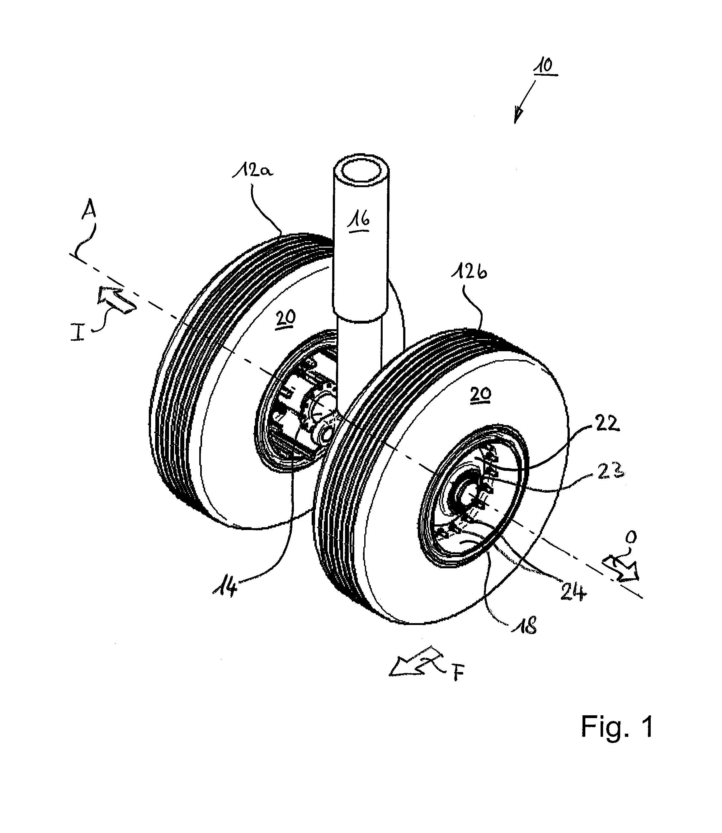
[0054]FIG. 1 shows a three-dimensional representation of an undercarriage 10—also known as landing or running gear—of an airplane (not shown) according to one aspect of the present invention.

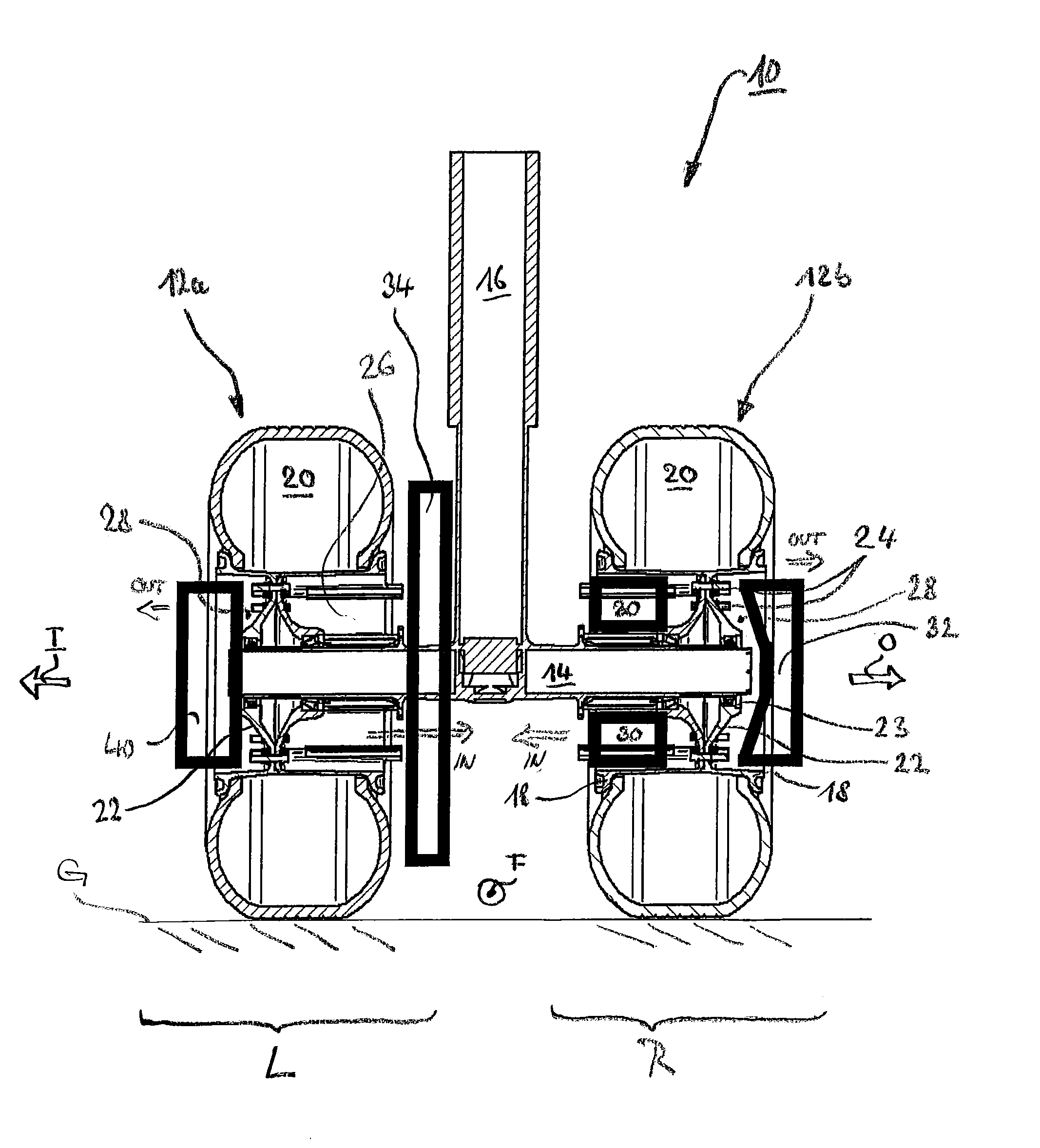
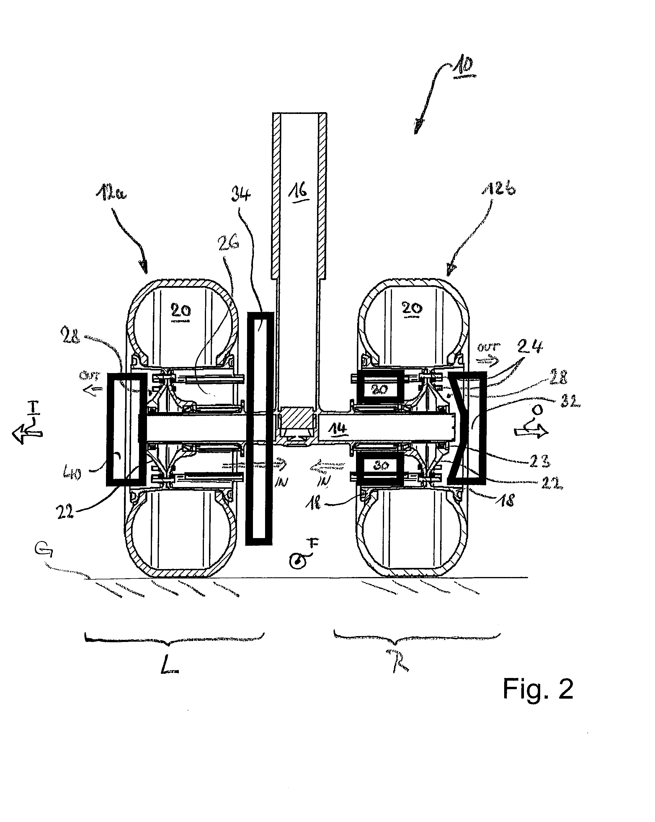
[0055]The undercarriage 10 comprises a first ground wheel 12a and a second ground wheel 12b, which are rotatably mounted on an axle 14 of the undercarriage 10. The undercarriage 10 further comprises a leg formed by a strut 16 as the major mechanical element for transferring the weight and other loads during landing, taxiing and take-off of the airplane via the undercarriage and the ground wheels attached thereto into the ground G (FIG. 2).

[0056]Further each of the ground wheels 12a, 12b comprises a rim 18 for installation or receiving of a respective tire 20. The rim 18 is further connected to a disk 22 which is attached to a hub 23 in any suitable manner that allows for a rotatable fixed attachment between the ground wheel and the axle 14 of the undercarriage 10.

[0057]The rim 18 and the disk 22...


PUM


Abstract

A drive unit for an aircraft ground wheel associated with a brake unit for braking the ground wheel includes: a driving motor drivingly coupleable to the ground wheel; and a cooling system including at least a drive cooling unit configured to generate a drive cooling air stream for cooling the drive unit and a brake cooling unit configured to generate a brake cooling air stream by sucking in air from the brake unit. A method of controlling such drive unit in which the cooling system is driven by the driving motor of the drive unit includes: decoupling the driving motor from the ground wheel and increasing the rotational speed of the driving motor to increase the amount of generated drive cooling air, when an operating condition of the ground wheel and/or of the drive unit is switched from a propulsion mode to a non-propulsion mode.

Description

RELATED APPLICATIONS[0001]The present application claims the benefit under 35 U.S.C. §371 of International Patent Application No. PCT / EP / 2012 / 053106, having an international filing date of Feb. 23, 2012, and entitled “DRIVE UNIT FOR AIRCRAFT LANDING GER WITH INTEGRATED COOLING,” the entire content of which is incorporated herein by reference.FIELD[0002]The present invention relates in general to a drive unit for an aircraft running gear and to an aircraft running gear comprising a drive unit. In more detail, the present invention is directed to the integration of cooling means for dissipating heat produced by the drive unit and / or other devices associated with the running gear, such as a brake unit of the running gear.BACKGROUND[0003]Aircraft—also referred to as airplanes herein—use their main engines such as gas turbine, turbo-fan or turbo-prop engines for taxiing on the ground, usually on an airfield or a maneuvering area of an airport. As the main engines of airplanes are not des...

Claims


Application Information

Patent Timeline
Patent Type & Authority Applications(United States)
IPC IPC(8): B60T5/00B64C25/42B64C25/40
CPCB60T5/00B64C25/42B64C25/405Y02T50/80B64C25/40
Inventor MUELLER, ANTONOSWALD, JOHANN
Owner L 3 COMM MAGNET MOTOR
Why Eureka
Try Eureka