Plasma Confinement Device

a technology of confinement device and plasma, which is applied in the field of confinement device of ionized gas (plasma) and can solve the problems of failure to stably hold plasma for periods of time viable to commercial interest, date, and device for confinement of plasma in magnetic field

Inactive Publication Date: 2015-04-09
PRATER DANIEL
View PDF0 Cites 5 Cited by
  • Summary
  • Abstract
  • Description
  • Claims
  • Application Information

AI Technical Summary

Benefits of technology

[0010]The present invention provides magnetic mirror confinement of plasma in the annular region interior to magnetic field coils. The basic geometry of these magnetic field coils is a stack, or cylindrical column, each coil of the stack alternating in field polarity in relation to adjacent coil and each electrode adjacently interior to each field coil also alternating in polarity in relation to adjacent electrodes. Alternation in magnetic field polarity is accomplished either by alternating direct current direction or by alternating coil-winding direction. Alternately, the coils may be formed of conductive plates

Problems solved by technology

Devices for confinement of plasma in a magnetic field have, prior to date, failed to stably hold plasma for periods of time viable to commercial interest primarily due to formation of plasma instabilities.
This design, as are the other coaxial solenoid field coils designs of, for instance U.S. Pat. No. 3,189,523 to Patrick, is unable to achieve a sufficient mirror ratio,

Method used


Image

  • Plasma Confinement Device
  • Plasma Confinement Device
  • Plasma Confinement Device

Examples


example

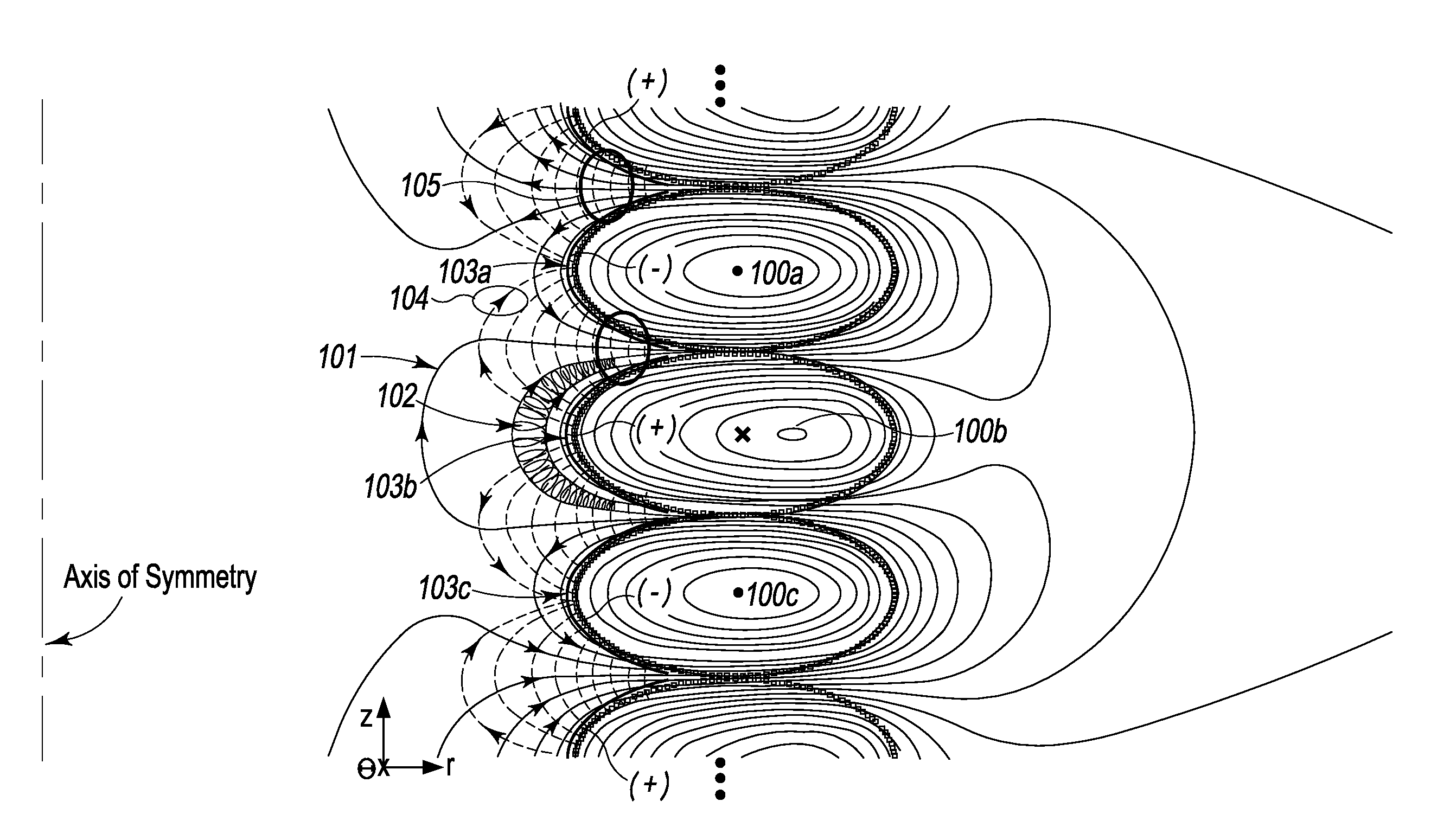
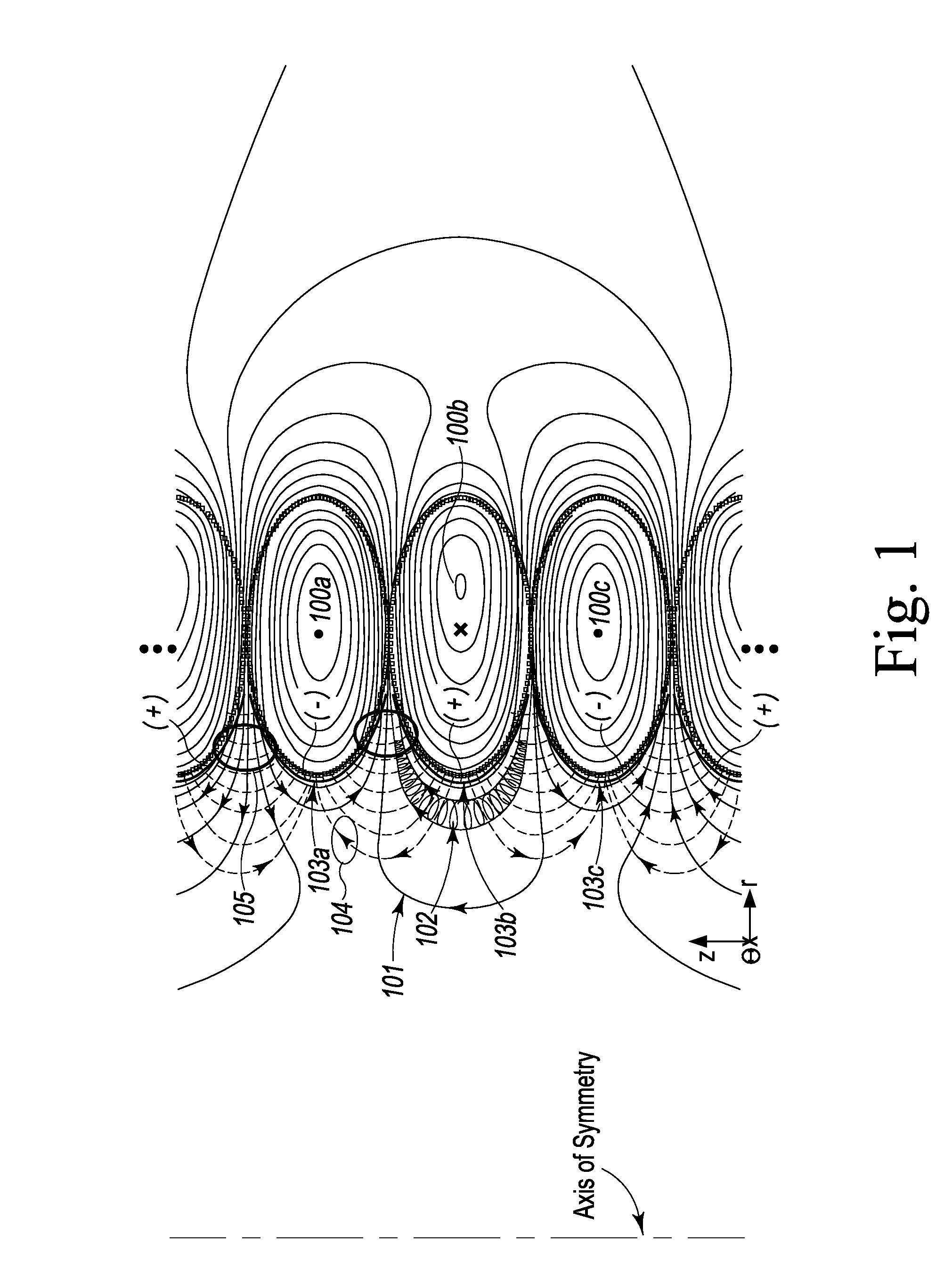
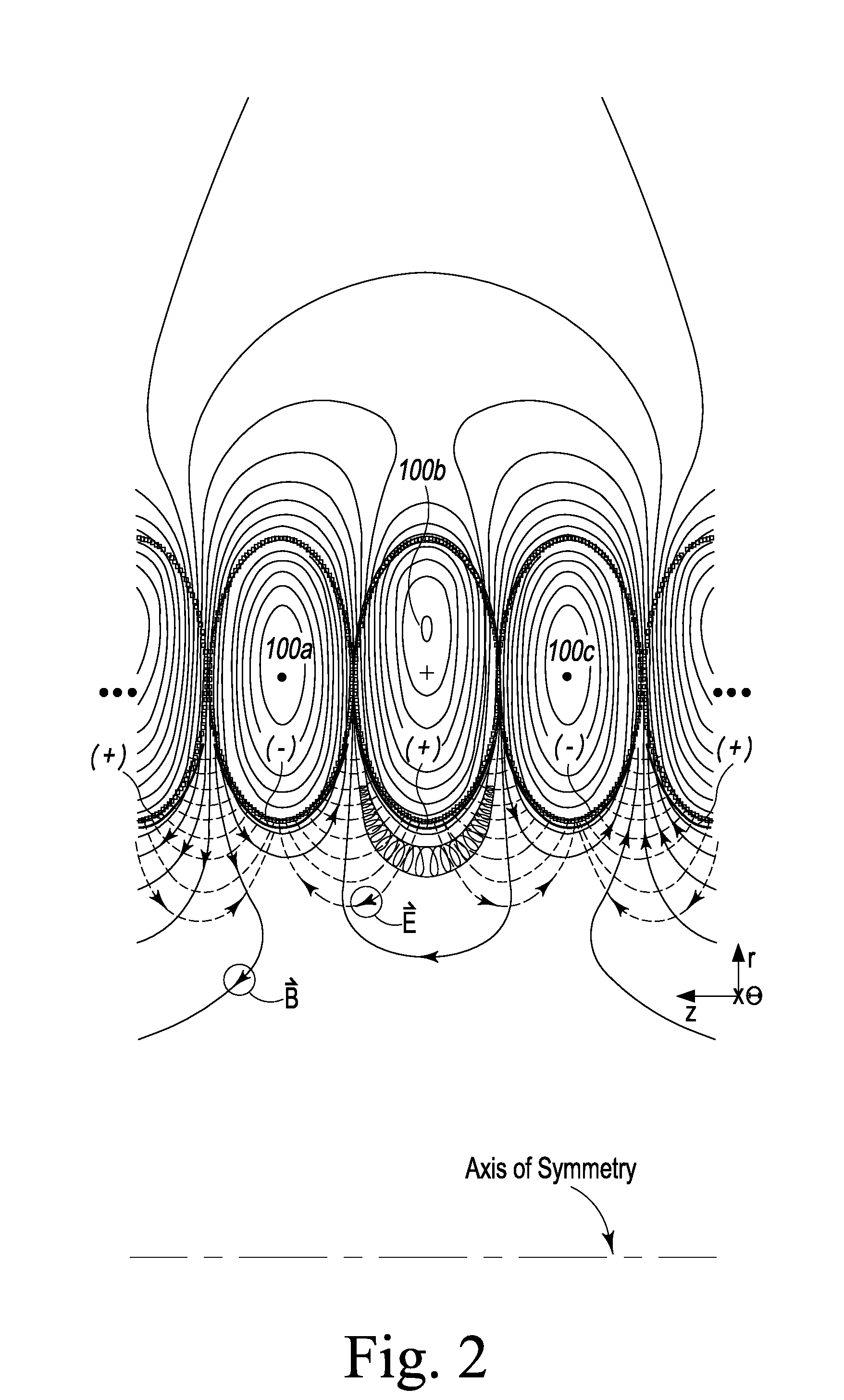
[0030]One embodiment of the present invention, as shown in FIG. 1 a simplified example of a real-world device, 25-cm radius by 50-cm radius ellipse (in axial cross-section) of at minimum three field coils of 12-gauge copper magnet wire are wound to approx. 90% fill (using hexagonal packing of approx . . . 106700 turns) and carry 102A current or 108A current in the opposing direction, respectively, alternating from center coil outward. The resulting magnetic field at 10 cm interior of the inner wall of the center coil, along its equatorial plane, is approx. 1.85 Tesla and along that field line can achieve a mirror ratio of 3.3. An electric field of 10800 V / m at the aforementioned point induces azimuthal rotation of approx. 5838 meters / second. Alternatively the magnetic field coils may be of any cross-sectional shape, for example, ellipses with major axes in the radial direction and minor axes in the axial direction, or square, to simplify construction, or any shape. It is an object o...


PUM


Abstract

A device and method for magnetic field confinement of plasma is formed by a cylindrically stacked column of direct current-carrying magnetic field coils with electrodes adjacently interior to each magnetic field coils so as to induce plasma rotation about an annular confinement region. Each field coil produces a magnetic field alternating in direction relative to adjacent coils and, so as to maintain consistent overall azimuthal direction of plasma rotation, electric field electrodes alternate accordingly in polarity along the axial length of the device. The device may be used for inducing nuclear fusion, for the ionic or isotopic separation of elements, creation of thrust by ejecting mass along the axial direction of the device, for creating a gravitational acceleration field, and for creating a state change beyond plasma.

Description

CROSS-REFERENCE TO RELATED APPLICATIONS[0001]This non-provisional patent application claims the benefit of and / or priority under 35 U.S.C. ♀119 to U.S. Provisional Patent Application Ser. No. 61 / 886,470 filed Oct. 3, 2013, entitled “Plasma Containment Device”, U.S. Provisional Patent Application Ser. No. 61 / 986,263 filed Apr. 30, 2014, entitled “Coaxial Mirror Confinement of Plasma”, and U.S. Provisional Patent Application Ser. No. 62 / 027,882, entitled “Device For Plasma Containment”, the entire contents of each one of which are specifically incorporated herein by this reference.FIELD OF THE INVENTION[0002]The present invention relates in general to the subject of ionized gas (plasma) confinement, and specifically, to confinement of rotating plasma in a magnetic field where rotation is established by the interaction of plasma with an electric field disposed intersecting the magnetic field.BACKGROUND OF THE INVENTION[0003]Devices for confinement of plasma in a magnetic field have, pr...

Claims


Application Information

Patent Timeline
IPC IPC(8): H05H1/16
CPCH05H1/16H05H1/14
Inventor PRATER, DANIEL
Owner PRATER DANIEL
Why Eureka
Try Eureka