Wireless charger with coil position adjustability

a technology of wireless chargers and coils, applied in the direction of electric power, electric vehicles, transportation and packaging, etc., can solve the problems of inconvenient preparation and carrying of battery chargers with different designs and specifications, predetermined position of induction coils in commercial wireless chargers, and large increase in wireless charger manufacturing costs. achieve the effect of smooth and stable operation

Inactive Publication Date: 2015-04-09
CYBER POWER SYST
View PDF7 Cites 39 Cited by
  • Summary
  • Abstract
  • Description
  • Claims
  • Application Information

AI Technical Summary

Benefits of technology

[0010]Further, the base member comprises an extension plate obliquely upwardly extended from a rear top side thereof, and two guide rails mounted at the extension plate and respectively in a parallel manner. Further, the push-pull unit comprises two sliding ways respectively located at two opposite lateral

Problems solved by technology

However, it is inconvenient to prepare and to carry battery chargers with different designs and specifications for different charging applications.
However, the position of an induction coil in any commercial wireless charger is predetermined and not adj

Method used


Image

  • Wireless charger with coil position adjustability
  • Wireless charger with coil position adjustability
  • Wireless charger with coil position adjustability

Examples


Embodiment Construction

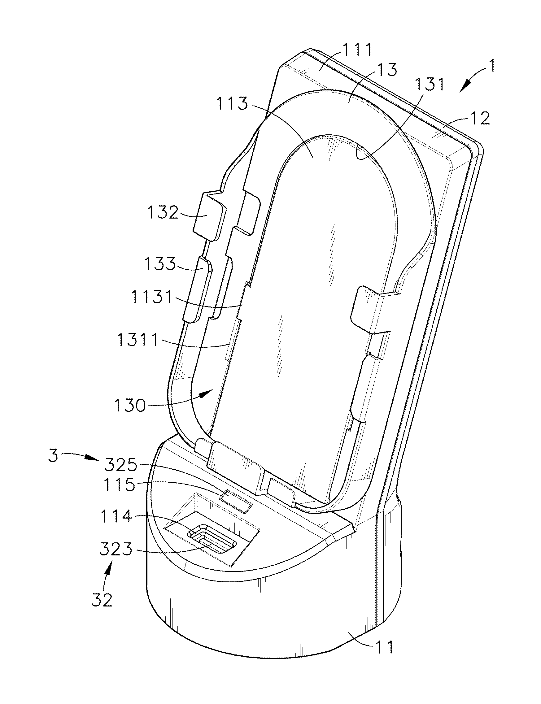
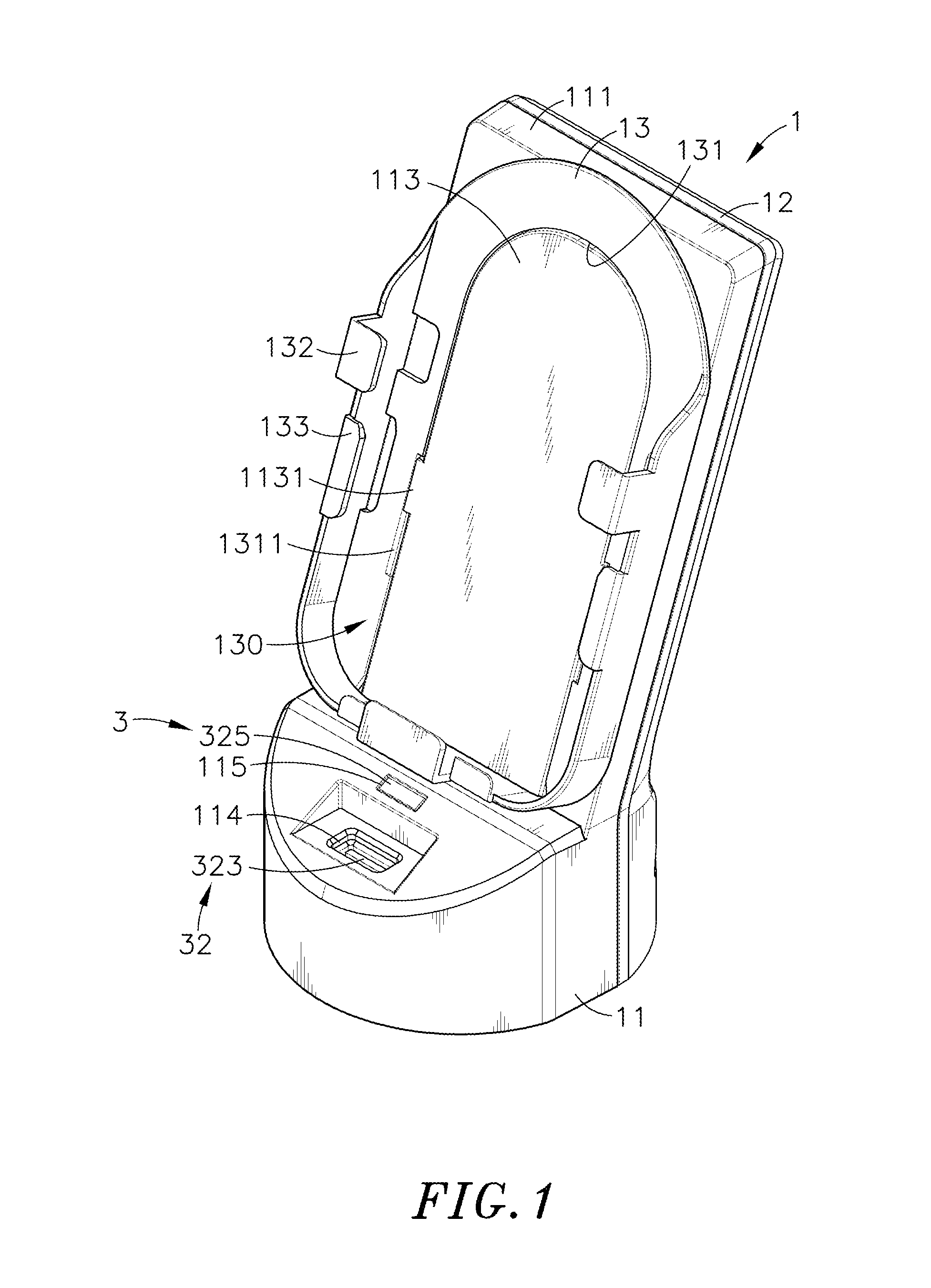
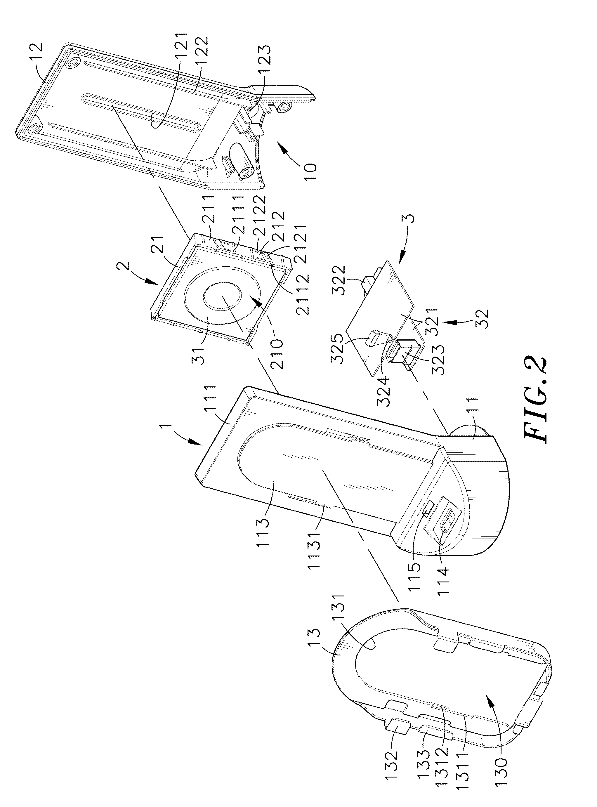
[0021]Referring to FIGS. 1-4, a wireless charger with coil position adjustability in accordance with the present invention is shown. The wireless charger comprises a base unit 1, a push-pull unit 2, and a power supply unit 3.

[0022]The base unit 1 comprises a base member 11, a back cover 12, and a rack 13. The base member 11 comprises an extension plate 111 obliquely upwardly extended from a rear top side thereof, a sliding space 110 defined in a back side of the extension plate 111, two guide rails 112 mounted at the back side of the extension plate 111 and respectively extended along two opposite lateral sides of the sliding space 110 in a parallel manner, and a plurality of position-limit grooves 1121 transversely formed in the guide rails 112 and spaced along the length of the guide rails 112.

[0023]The back cover 12 is fixedly fastened to the back side of the base member 11 by, for example, screws. Alternatively, hook joint, adhesive or laser welding may be employed to affix the ...


PUM


Abstract

A wireless charger includes a base unit including a base member and a rack mounted at the base member for holding a mobile electronic device, a push-pull unit including a sliding seat mounted in the base member and slidable along a predetermined sliding path and automatically lockable to the base member at an adjusted position, and a power supply unit including a power-supplying coil mounted in the sliding seat and a circuit module mounted in the base member and electrically connected with the power-supplying coil for controlling the power-supplying coil to create an alternating electromagnetic field for enabling a power-receiving coil of a loaded mobile electronic device to take power from the electromagnetic field and to convert it back into electrical current for charging a battery in the mobile electronic device.

Description

BACKGROUND OF THE INVENTION[0001]1. Field of the Invention[0002]The present invention relates to wireless charging (inductive charging) technology, and more particularly to a wireless charger with coil position adjustability, which allows adjustment of the power-supplying coil to match with the configuration of a power-receiving coil in a mobile electronic device to be charged, achieving best charging performance.[0003]2. Description of the Related Art[0004]The rapid development of electronic and multimedia technologies has brought people remarkable convenience into people's lives. Nowadays, it is the market trend to create smart phone, tablet computer, digital camera, multimedia player and many other mobile electronic devices with light, thin, short and small characteristics.[0005]For mobile application, an electronic device must overcome the problem of power supply consumption. A mobile electro device generally uses a rechargeable battery to provide the necessary working electric ...

Claims


Application Information

Patent Timeline
IPC IPC(8): H02J7/02
CPCH02J7/025H02J7/0044H02J50/90H02J50/005H02J50/10H02J7/02
Inventor CHEN, CHIH-MING
Owner CYBER POWER SYST
Why Eureka
Try Eureka