Planar array antenna structure

Inactive Publication Date: 2015-04-09
TECOM
View PDF4 Cites 7 Cited by
  • Summary
  • Abstract
  • Description
  • Claims
  • Application Information

AI Technical Summary

Benefits of technology

[0007]An object of the present disclosure is to provide a planar array antenna structure to solve the above-mentioned problems. Accordingly, a plurality of antenna units are disposed on the substrate in a s

Problems solved by technology

Further, it is inconvenient to operate the communication device because of a reserved installation space inside the communication device.
In addition, the array antenna struct

Method used


Image

  • Planar array antenna structure
  • Planar array antenna structure
  • Planar array antenna structure

Examples


Example

[0051]Reference will now be made to the drawing figures to describe the present invention in detail.

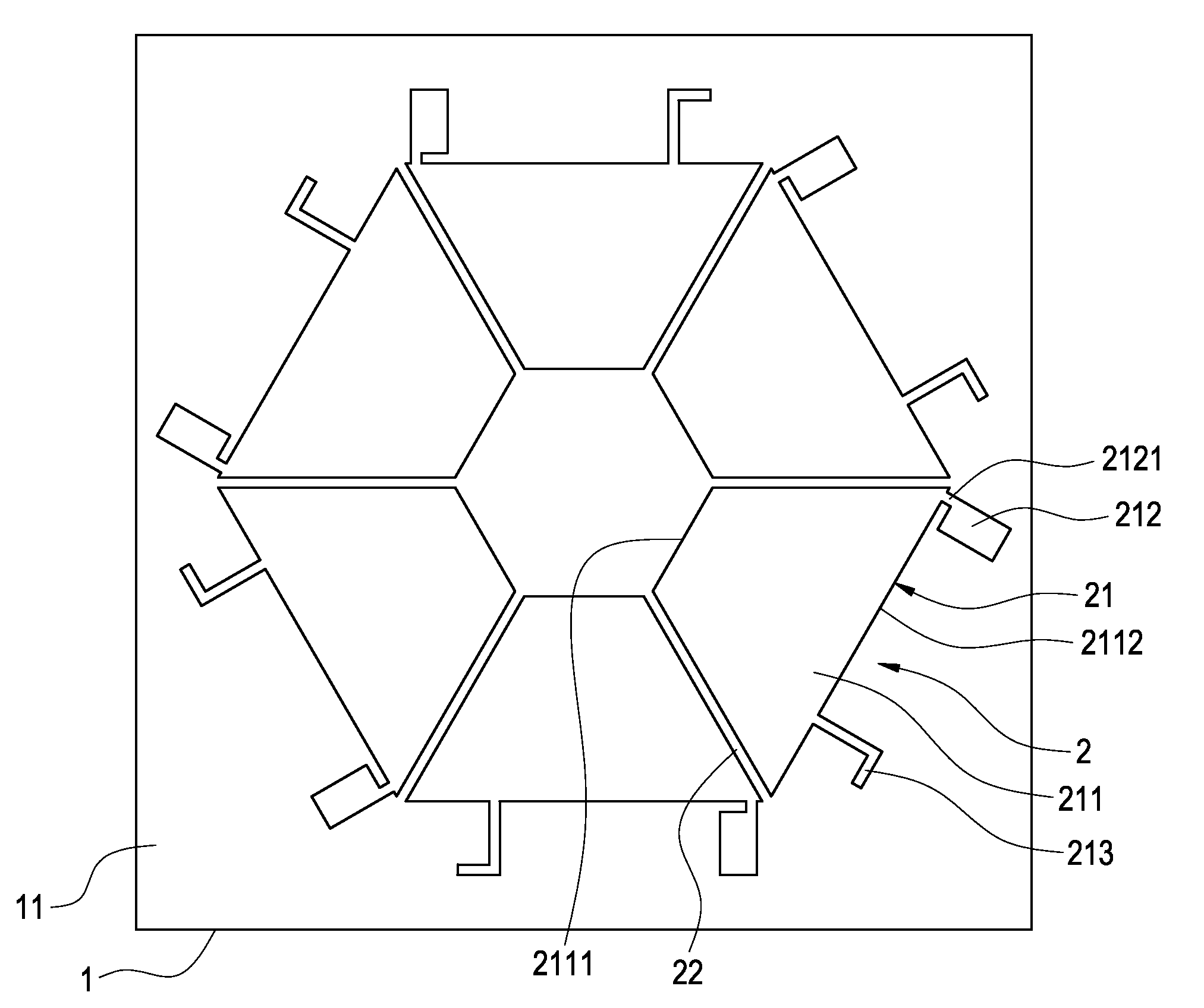
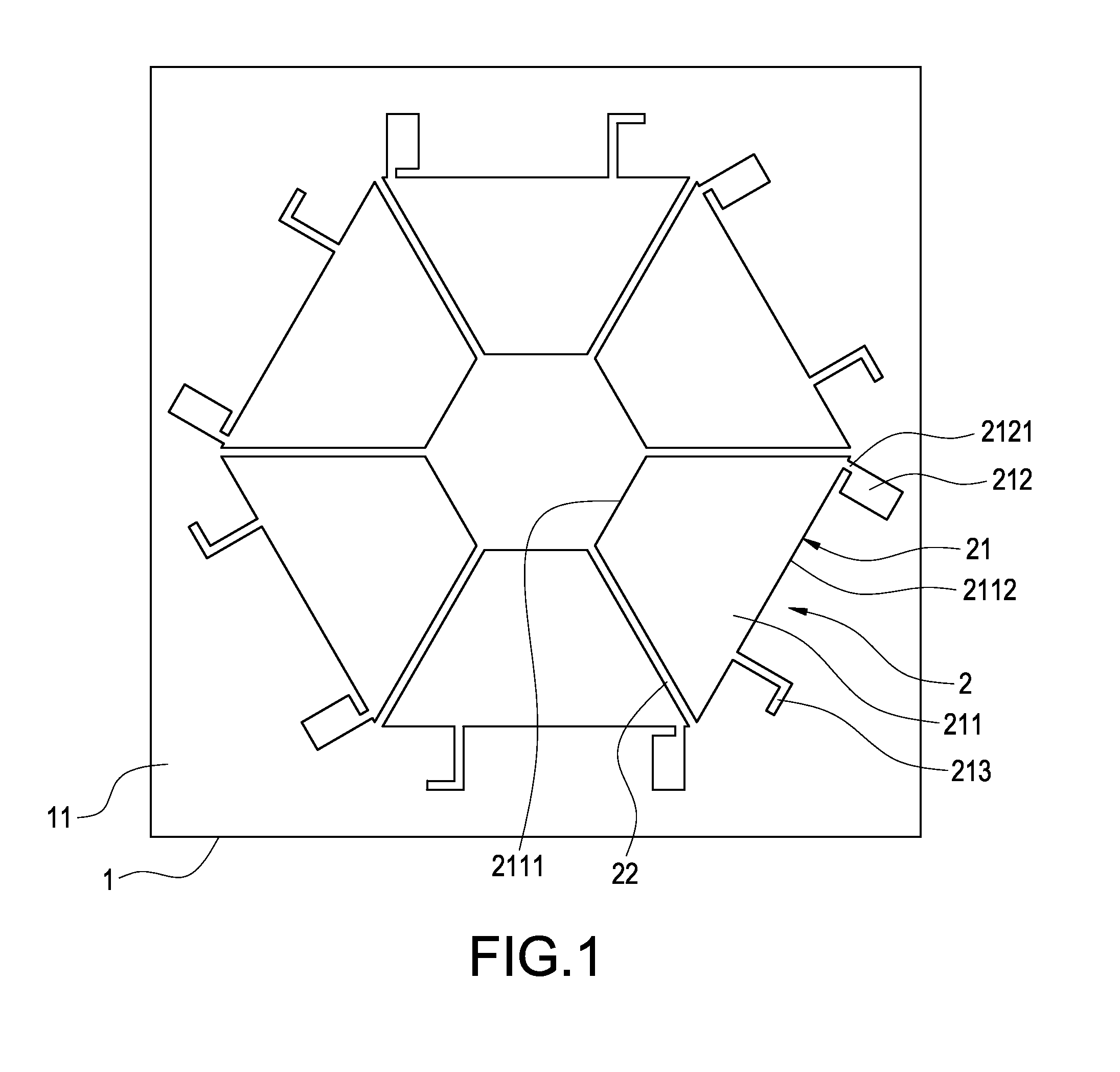
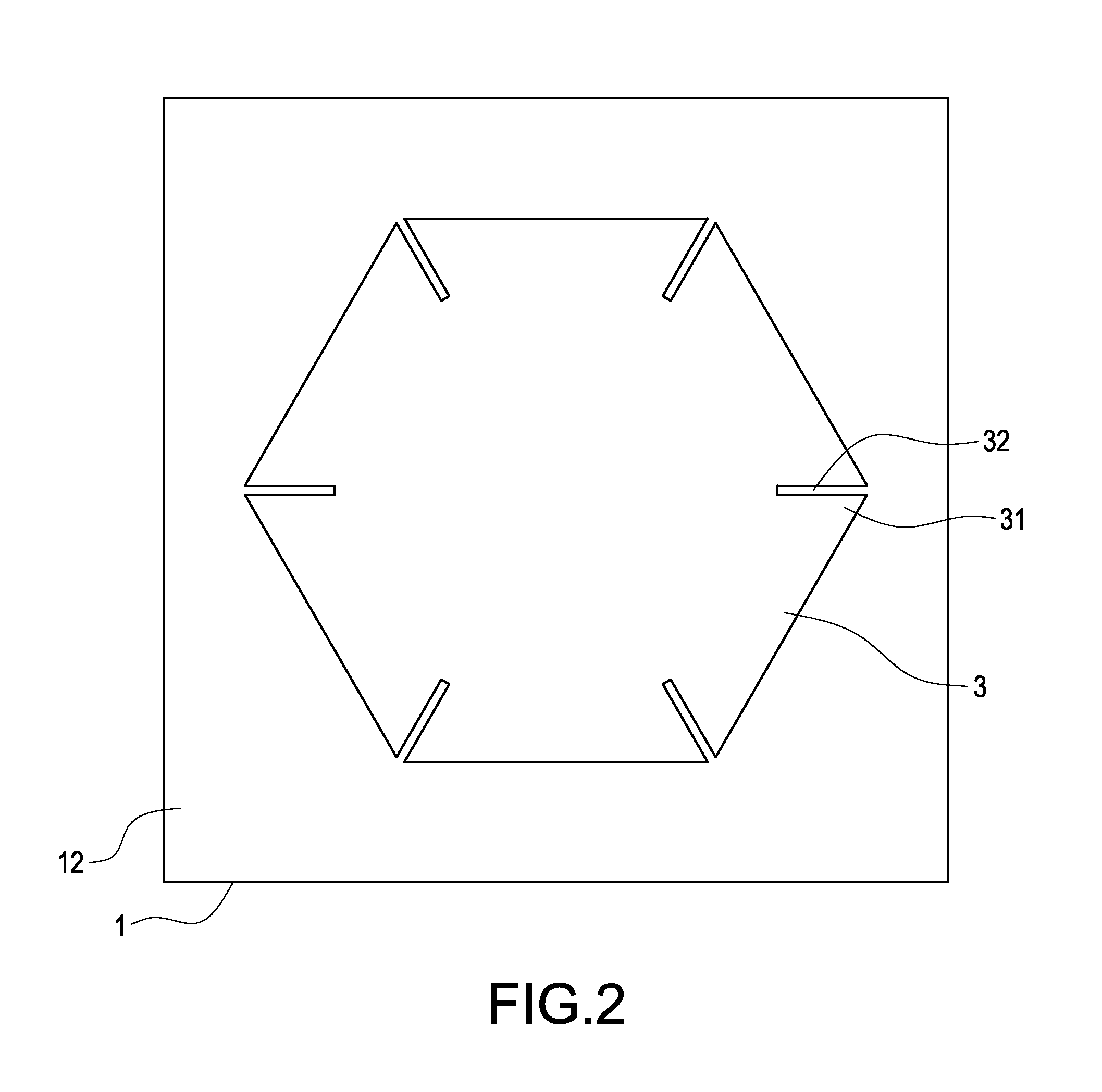
[0052]Reference is made to FIG. 1, FIG. 2, and FIG. 3 which are a schematic front view, a schematic rear view, and a schematic view of a substrate of a planar array antenna structure according to the present disclosure. The planar array antenna structure includes a substrate 1, an array antenna 2, and a bottom ground portion 3.

[0053]The substrate 1 has a front surface 11 and a rear surface 12. In particular, the substrate I is a polyester fiberglass board.

[0054]The array antenna 2 is composed of a plurality of antenna units 21 and disposed on the front surface 11 of the substrate 1, and the antenna units 21 are disposed on the front surface 11 of the substrate 1 in a symmetrical and polygonal arrangement. Also, a spaced slot 22 is formed between every two antenna units 21. Each antenna unit 21 includes a top ground portion 211, a main radiator 212, and an auxiliary radiator 213. The t...


PUM


Abstract

A planar array antenna structure includes a substrate, an array antenna, and a bottom ground portion. The substrate has a front surface and a rear surface. The array antenna is composed of a plurality of antenna units and disposed on the front surface of the substrate in a symmetrical and polygonal arrangement. A spaced slot is formed between every two antenna units. The bottom ground portion is polygonal and arranged on the rear surface of the substrate. The bottom ground portion has a plurality of included angles thereon, and one notch is formed between two included angles and the notches are correspondingly arranged to the spaced slots. Accordingly, the planar array antenna structure is used to generate high-gain radiation variations, effectively restrain the isolation between the radiators, and significantly increase overall performance of the antenna.

Description

BACKGROUND[0001]1. Technical Field[0002]The present disclosure relates generally to an antenna, and more particularly to a planar array antenna structure is operated at 5 to 6 GHz.[0003]2. Description of Prior Art[0004]In antenna communication, multi-input and multi-output, or MIMO is the use of multiple antennas at both the transmitter and receiver to improve communication performance. That is, spatial multiplexing and multiple antennas are adopted to transmit and receive multiple data streams through the same frequency channel. The MIMO is applied to. the wireless LAN (WLAN) system to increase data rate of IEEE 802.11a or 802.11G by using two transmitting antennas.[0005]In order to implement the MIMO antenna wireless communication system, the array antenna structure is adopted. TW patent No. M441940 discloses an array structure to provide multiple antenna radiators with same shape by the sheet metal stamping technology. Further, at least three antenna radiators are arranged to sta...

Claims


Application Information

Patent Timeline
IPC IPC(8): H01Q21/28
CPCH01Q21/28H01Q1/523H01Q9/42H01Q21/205
Inventor HSU, WEN-HSIENHSU, WEN-HSIUWEN, CHUNG-HSUANCHAO, SHANG-CHUN
Owner TECOM
Why Eureka
Try Eureka