Lens assemblies and optical systems incorporating lens assemblies

a technology of lens elements and optical systems, applied in the field of lens assemblies, can solve problems such as misalignment of lens elements relative and contamination of equipmen

Active Publication Date: 2015-04-09
CORNING INC
View PDF6 Cites 4 Cited by
  • Summary
  • Abstract
  • Description
  • Claims
  • Application Information

AI Technical Summary

Problems solved by technology

However, in some applications, the light introduced to the lens elements may tend to degrade a bonding agent that is positioned to couple the lens element to a lens holder.
Degradation of the bonding agent may lead to contamination of the equipment and / or misalignment of the lens element relative to the light source.

Method used


Image

  • Lens assemblies and optical systems incorporating lens assemblies
  • Lens assemblies and optical systems incorporating lens assemblies
  • Lens assemblies and optical systems incorporating lens assemblies

Examples


Embodiment Construction

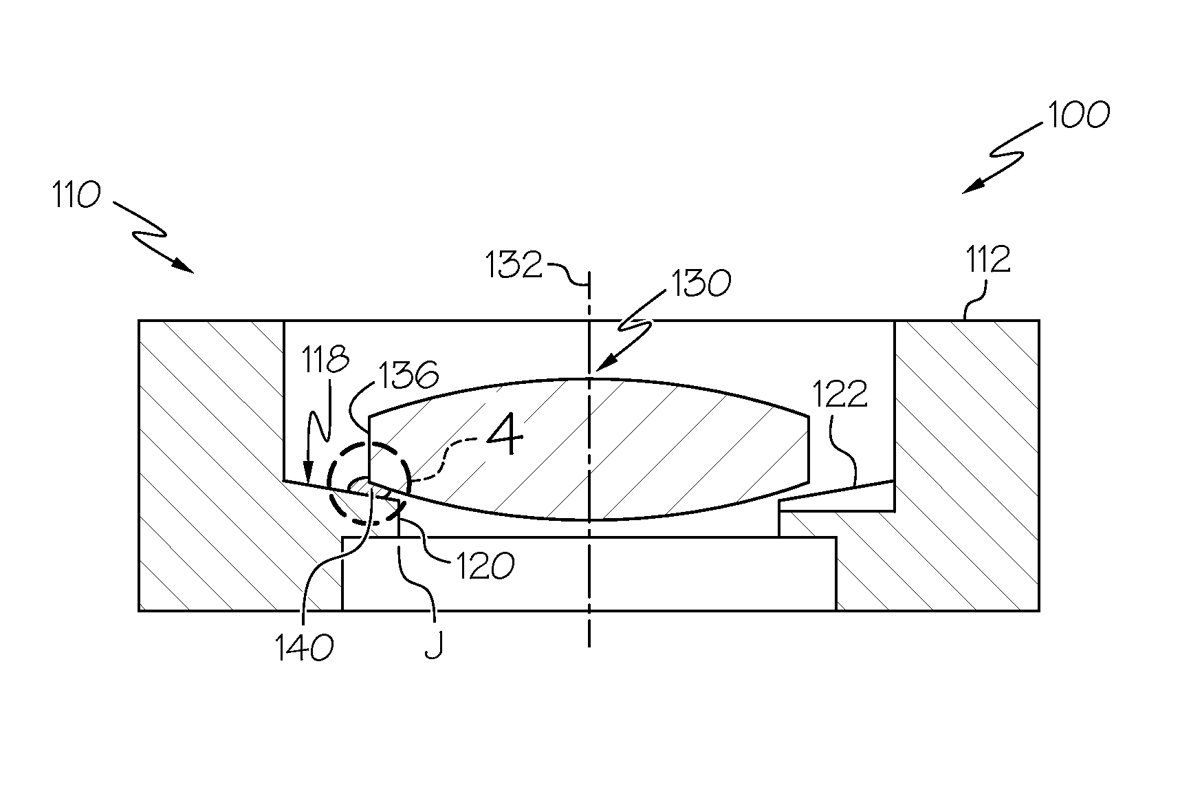
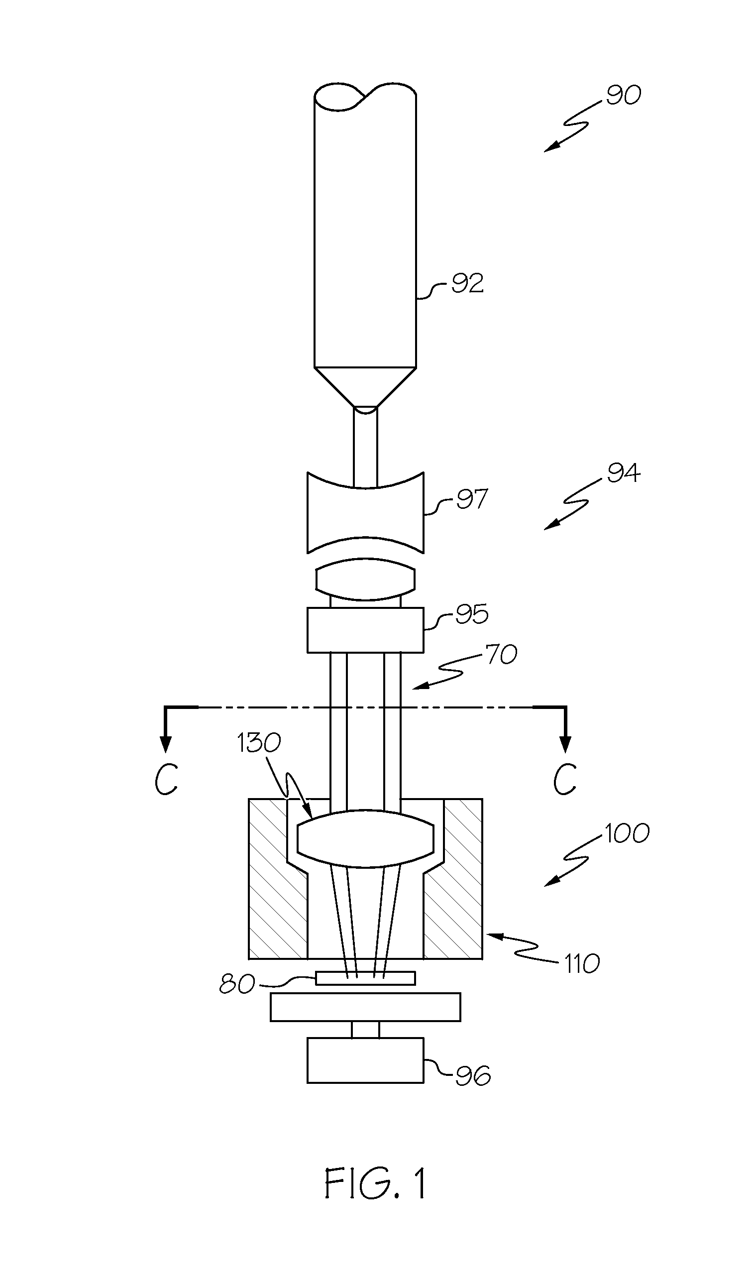
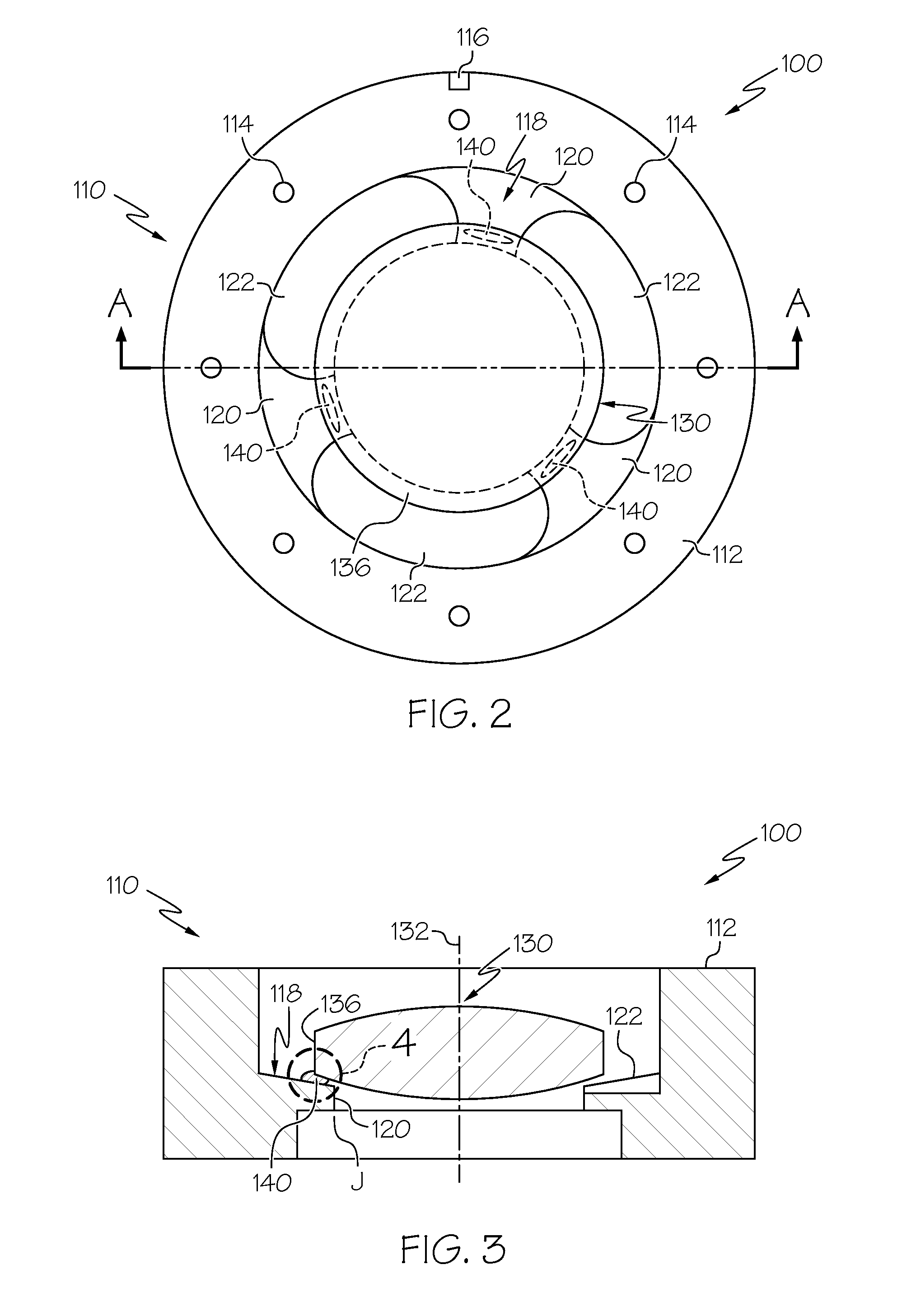
[0021]Reference will now be made in detail to embodiments of lens assembly having optical lenses and lens holders and optical systems that incorporate lens assemblies having optical lenses and lens holders. One embodiment of an optical system incorporating a lens assembly having an optical lens and a lens holder. The optical lens is secured to the lens holder by a bonding agent. The bonding agent is arranged in an interrupted configuration at positions proximate to a circumference of the optical lens. The lens assembly including the optical lens and the lens holder may be incorporated into an optical system, along with a light source that provides light to the optical lens. The light provided by the light source has an optical footprint that includes a plurality of high-intensity regions and a plurality of low-intensity regions. The lens assembly is positioned in a circumferential orientation such that the bonding agent is spaced apart from the high-intensity regions of the optical ...


PUM

PropertyMeasurementUnit
circumferenceaaaaaaaaaa
optical axisaaaaaaaaaa
structureaaaaaaaaaa

Abstract

An optical system includes a lens assembly and a light source. The lens assembly includes an optical lens positioned to transmit and refract light provided by the light source, and a lens holder coupled to the optical lens and maintaining a position of the optical lens relative to the light source. The optical lens is coupled to the lens holder with a bonding agent arranged in an interrupted configuration at positions proximate to a circumference of the optical lens. The light source provides light to the optical lens of the lens assembly. The light provided to the optical lens has an optical footprint that includes a plurality of high-intensity regions separated from one another by low-intensity regions and the bonding agent is positioned in a circumferential orientation relative to the light source such that the bonding agent is spaced apart from the high-intensity regions of the optical footprint of the light.

Description

TECHNICAL FIELD[0001]The present specification generally relates to lens assemblies for positioning an optical lens relative to a light source.BACKGROUND[0002]Lens systems are used in a variety of end-user applications, including in lithography and semiconductor inspection equipment. In these applications, light from a light source is introduced to the lens elements to perform the manufacturing operation. However, in some applications, the light introduced to the lens elements may tend to degrade a bonding agent that is positioned to couple the lens element to a lens holder. Degradation of the bonding agent may lead to contamination of the equipment and / or misalignment of the lens element relative to the light source.[0003]Accordingly, alternative lens assemblies may be desired.SUMMARY[0004]In one embodiment, an optical system includes a lens assembly and a light source. The lens assembly includes an optical lens positioned to transmit and refract light provided by the light source,...

Claims


Application Information

Patent Timeline
Patent Type & Authority Applications(United States)
IPC IPC(8): G02B7/02G01N21/95G03F7/20
CPCG02B7/025G01N2201/061G01N21/9501G03F7/7015G03F7/70825
Inventor GREJDA, ROBERT DENNISHANFORD, KEITH ERNESTMAGIERSKI, KEVIN J.MCMICHAEL, TODD ROBERT
Owner CORNING INC
Why Eureka
Try Eureka