
Using gravity and piezoelectric elements to produce electric power

a piezoelectric element and gravity technology, applied in the direction of positive displacement liquid engine, piston pump, fluid coupling, etc., can solve the problems of consuming energy, increasing the area of the turbine, and little power can be generated per cubic inch of water flowing through the turbine per second, etc., to achieve the effect of increasing the amplitude, reducing the friction loss of pipes, and increasing system efficiency

Inactive Publication Date: 2015-04-16
NEWMAN EDWIN
View PDF10 Cites 3 Cited by
  • Summary
  • Abstract
  • Description
  • Claims
  • Application Information

AI Technical Summary

Benefits of technology

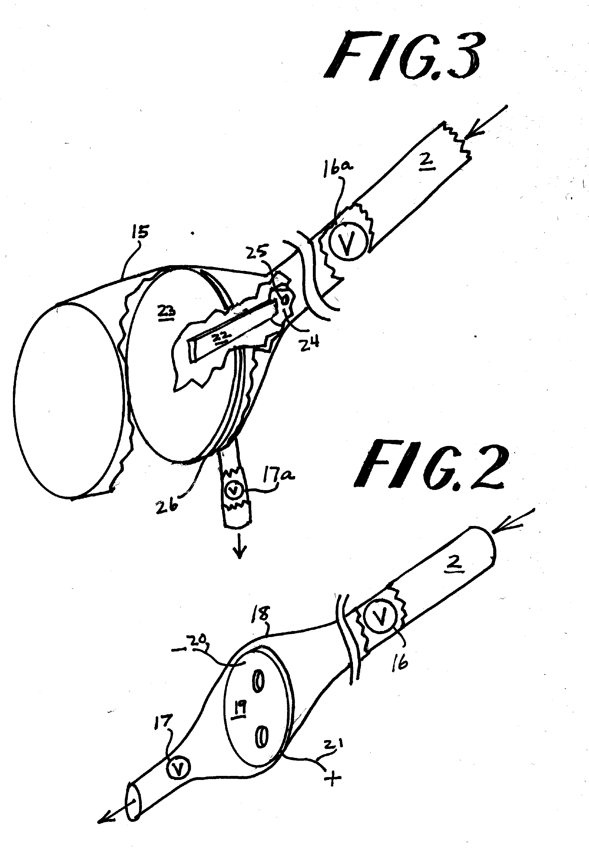
The invention described in this patent uses a piston, gear train, and electric generator to convert water pressure into electrical energy. The piston is driven by water pressure from a utility's water supply, and the system is designed to work efficiently at different elevations. The invention also includes a chamber full of water and containing piezoelectric material connected to the power grid, which can produce electricity by opening and closing valves to create waves of pressure on the piezoelectric elements. This alternative embodiment aims to enhance the possible electric output of piezoelectric elements and eliminate the need for turbines and generators in electric power production.

Problems solved by technology

Because a turbine has been used, very little power can be generated for each cubic inch of water flowing through the turbine per second unless the cross-sectional area of the turbine is increased to a prohibitive degree.
(U.S. Pat. No. 2,652,690) teaches a structure which will recycle the water flowing through the turbine but the recycling operation consumes energy.
Some thought has been given to convert ocean wave energy into electrical energy using piezoelectric elements, but the amplitude and frequency of the wave action is so low as to make this avenue of conversion impractical.

Method used


Image

  • Using gravity and piezoelectric elements to produce electric power
  • Using gravity and piezoelectric elements to produce electric power
  • Using gravity and piezoelectric elements to produce electric power

Examples


Embodiment Construction

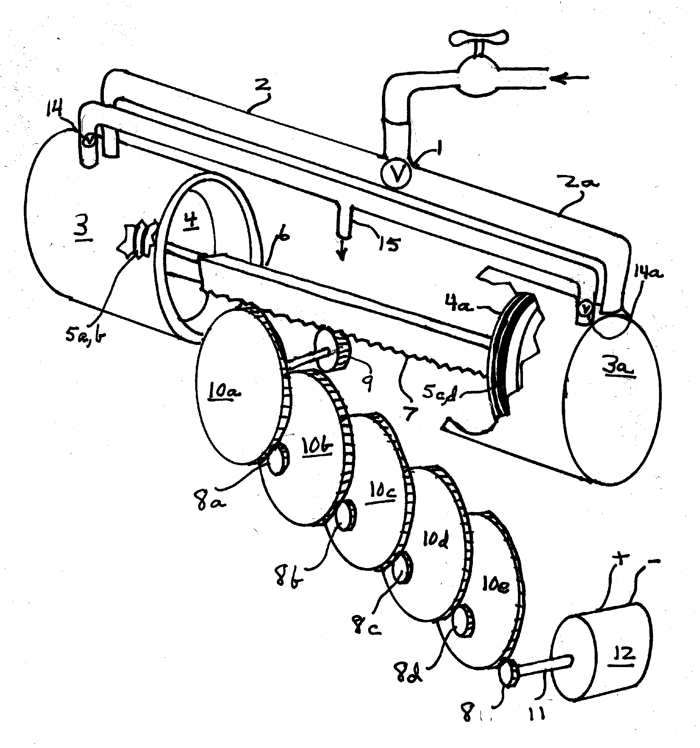
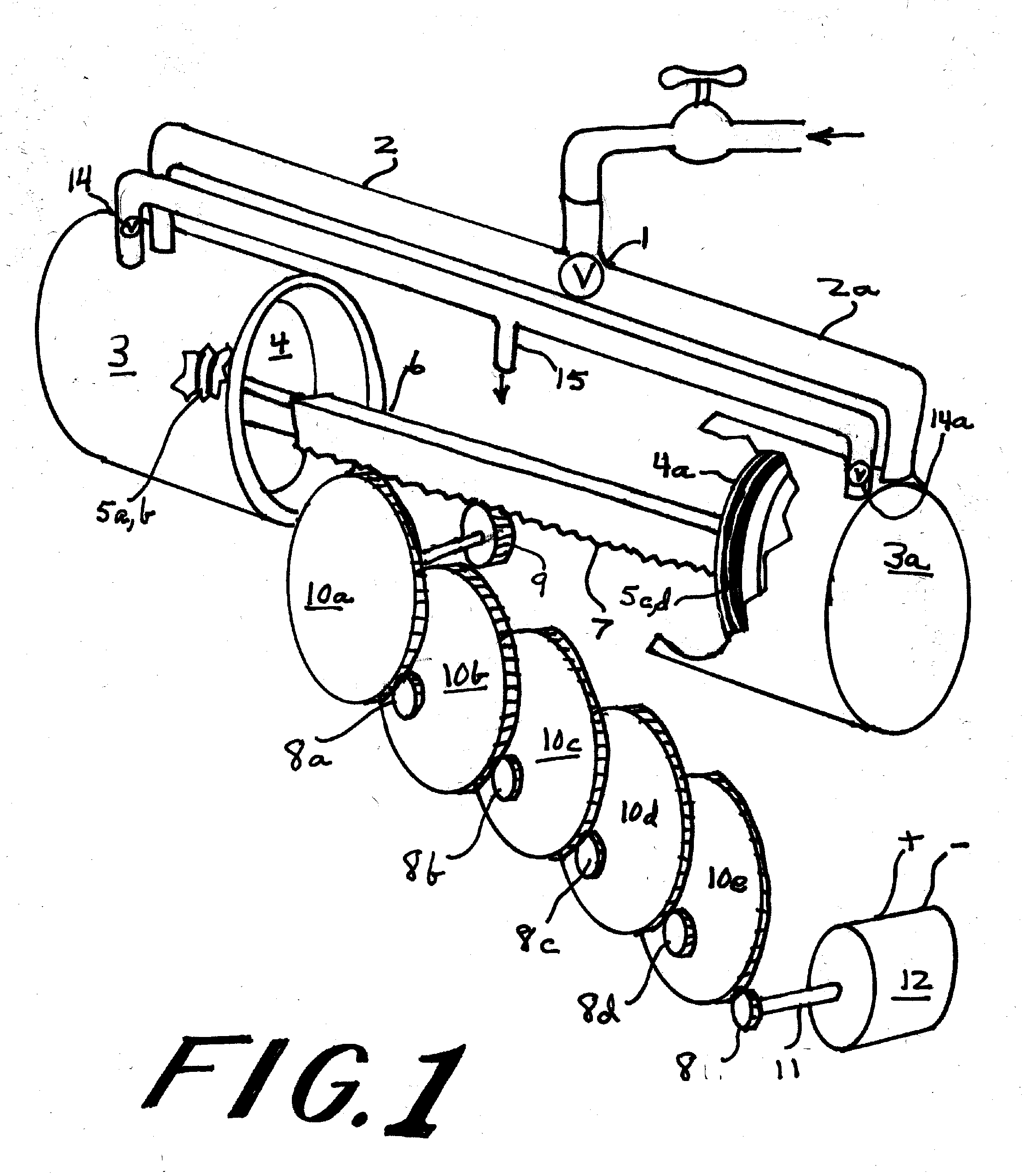
[0011]Pressurized water is made to move through valve 1 and either move through pipe 2 or 2a. This action forces either piston 4 or 4a to move shaft 6 to which gear rack 7 is fixedly attached. O-rings 5a-d seal the pistons for effective operation. Gear rack 7 is built to mesh with gear 9 which is shafted to rotate large spur gear 10a. which in turn is made to rotate a smaller spur gear 8a. Spur gear 8e is made to operate generator 12 through the agency of shaft 11 at a greater speed than the speed at which pistons 4,4a are made to move by the pressurized water.

[0012]In operation, as piston 4 comes to the end of its travel valve 1 is moved to cut off pressure to the back of piston 4 and introduce pressure to the back of piston 4a. This action causes check valve 14 to open and non-pressurized water from piston cylinder 3 to be evacuated through pipe 15 and be exhausted.

[0013]More pairs of spur gears used means that less water is exhausted and generator 12 is operated at a higher speed...


PUM


Abstract

A hydroelectric power plant comprising a pipe from a water source in a mountain range which is made to open into a much larger in diameter piston cylinder at a much lower elevation. The piston therein is driven by water pressure to drive a gear train operatively connected to an electric generator on its far end. The piston is made to move slowly under great force, while the generator is made to turn at a much greater velocity, producing electricity. Water pressure may be derived from some municipal water systems. Much less water is expended through the device than by using a turbine, as in U.S. Pat. No. 1,774,603. Instead of a piston, piezoelectric elements may be used with shut-off valves on either side of the elements. By alternating the operation of these valves intense pressure waves may be induced to produce electricity. This obviates the need for turbines and generators for hydroelectric power generation.

Description

[0001]This invention is a development of information in Provisional Application 61 / 854,118.BACKGROUND OF THE INVENTION[0002]Jackson., in U.S. Pat. No. 1,774,603, teaches that a turbine-operated generator may receive its operating fluid from a city's water supply system. In a modem version, Toto Corp. has been assigned the rights to U.S. Patent Application 2009 / 0026768. Because a turbine has been used, very little power can be generated for each cubic inch of water flowing through the turbine per second unless the cross-sectional area of the turbine is increased to a prohibitive degree. Another explanation is that since the potential energy of the water is converted into kinetic energy hydraulically a great deal of water is needed to operate a turbine. Labriola et al. (U.S. Pat. No. 2,652,690) teaches a structure which will recycle the water flowing through the turbine but the recycling operation consumes energy.[0003]It would be advantageous to increase the amount of electrical powe...

Claims


Application Information

Patent Timeline
Patent Type & Authority Applications(United States)
IPC IPC(8): F03C1/12F03C1/26
CPCF03C1/12F03C1/26F04B9/02
Inventor NEWMAN, EDWIN
Owner NEWMAN EDWIN
Learn More