Percussion Unit

Active Publication Date: 2015-04-16
ROBERT BOSCH GMBH
View PDF20 Cites 8 Cited by
  • Summary
  • Abstract
  • Description
  • Claims
  • Application Information

AI Technical Summary

Benefits of technology

[0010]Further, it is proposed that the control unit have a learning mode for determining at least one known load. In particular, the control unit, when in the learning mode, may learn constant loads, time-dependent loads and/or angle-dependent loads. For the loads, the control unit may have predefined functions, which have scaling parameters. In the learning mode, the percussion mechanism unit may average a rotational speed signal, in a time domain and in an angle domain, over known time-dependent and angle-dependent periods of stored functions for the loads, and set the scaling parameters such that the sum of the known loads results in a least possible deviation from the rotational speed signal. Preferably, a learning phase may be effected in the idling operating mode, in which the operating state to be identified by the control unit is absent. The known loads can be determined, advantageously, by the control unit. Loads that change over the service life of the percussion mechanism unit can be re-learned. This avoids the need for loads to be determined by the user and/or by persons skilled in the art.
[0011]It is proposed that the control unit have a dynamic model that is provided to estimate a driving torque of the drive unit. In particular, the control unit may have a dynamic model that is provided to estimate a driving torque of the motor, taking account of the electric power consumption of the motor. Preferably, the dynamic model takes account of a moment of inertia of the motor and/or the rotational speed of the motor and/or a flux-dependent motor constant and/or a friction constant and/or a linked flux and/or a load moment and/or a viscous frictional component and/or a turbulent frictional component. The dynamic model may take account of further influences, in particular also time-periodic and angle-periodic influences. A “flux” in this context is to be understood to mean an electromagnetic flux in the motor. The electromagnetic flux is dependent, in particular, on the electric power consumption of the motor and on the flux-dependent motor constant. The flux-dependent motor constant may be defined by a characteristic curve. The characteristic curve may be calculated, for example, by means of a finite-element model. Methods of determining a dynamic model for calculating a driving torque of a motor, taking account of the electric power consumption and the rotational speed, are known to persons skilled in the art. Preferably, the dynamic model is provi

Problems solved by technology

The control unit can take account of parameters that

Method used


Image

  • Percussion Unit
  • Percussion Unit
  • Percussion Unit

Examples


Embodiment Construction

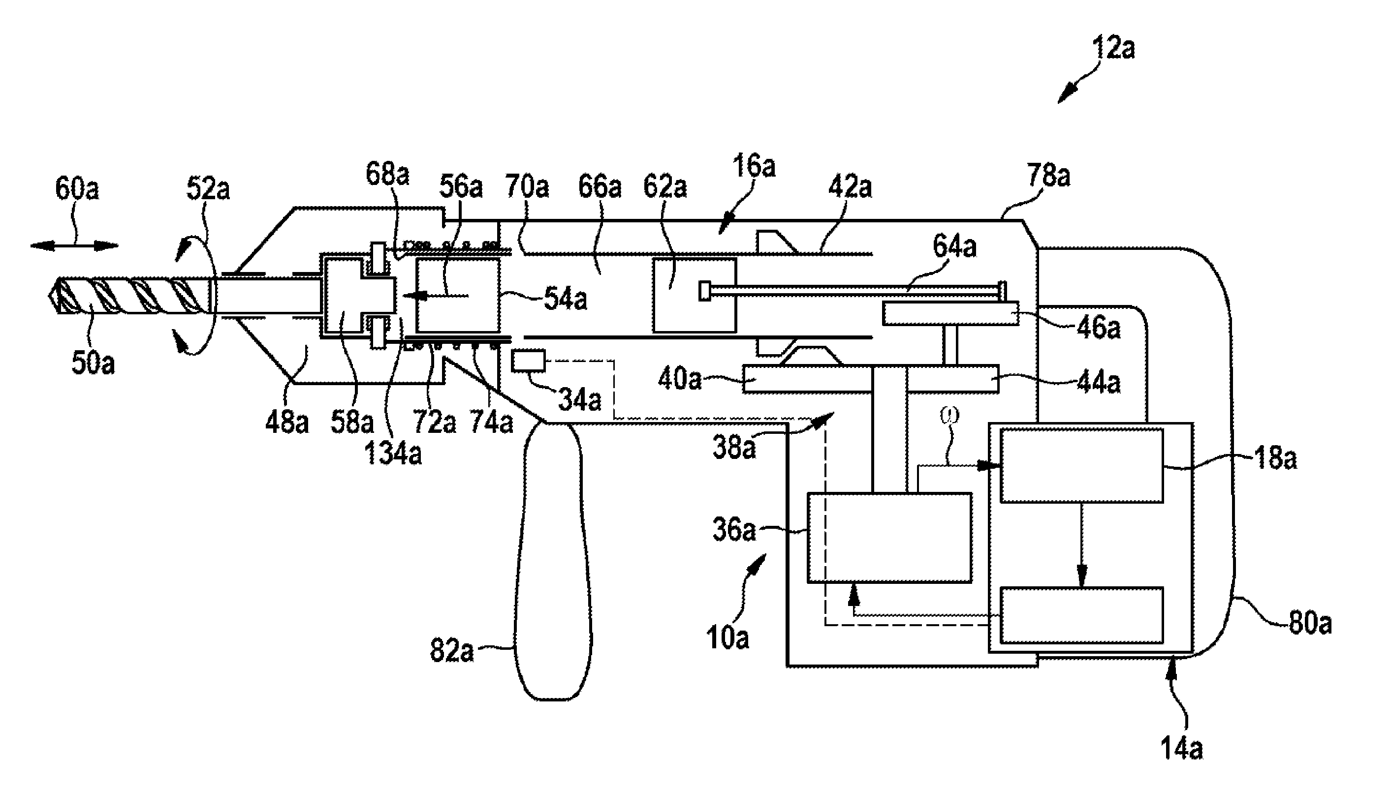
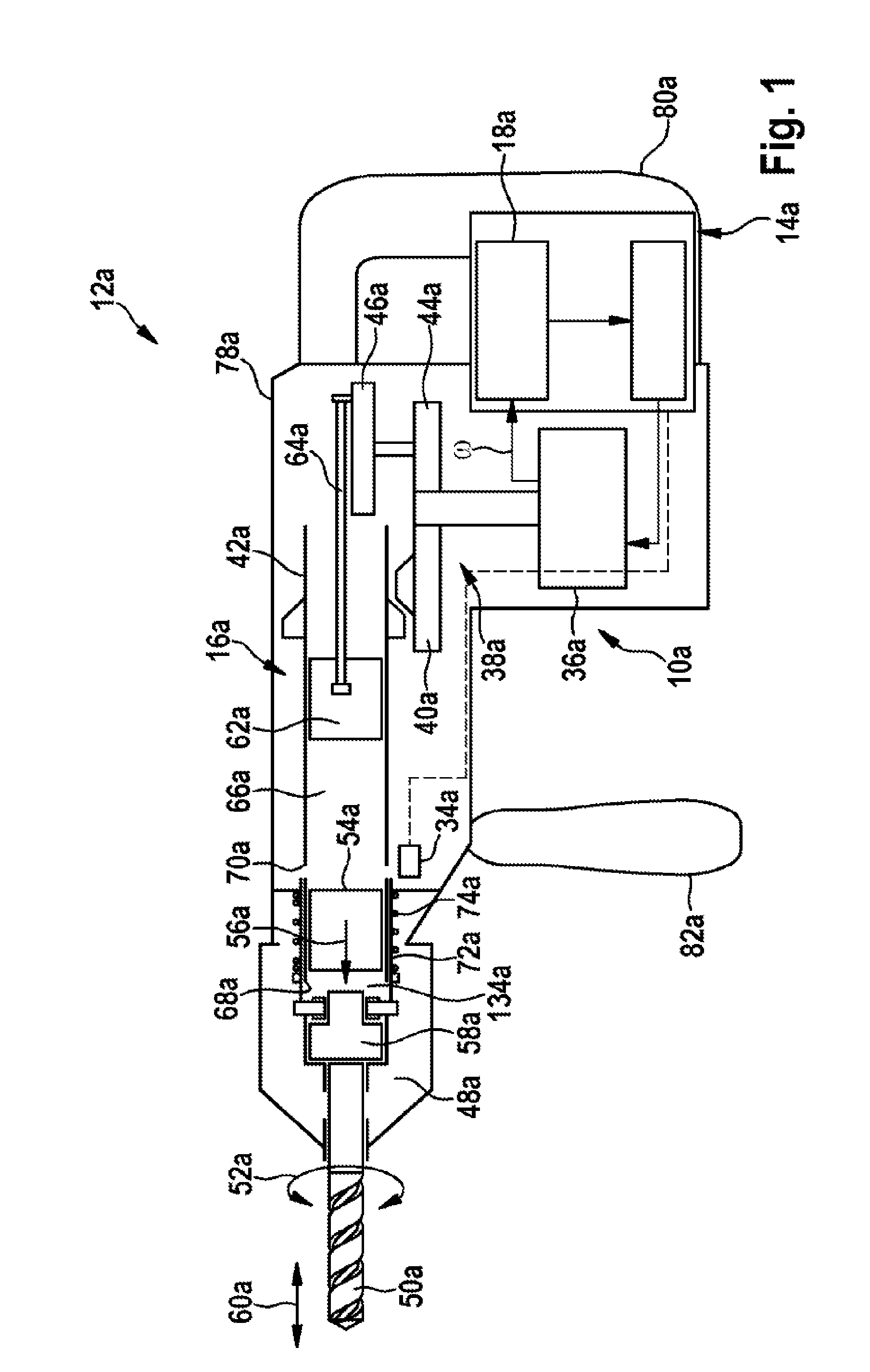
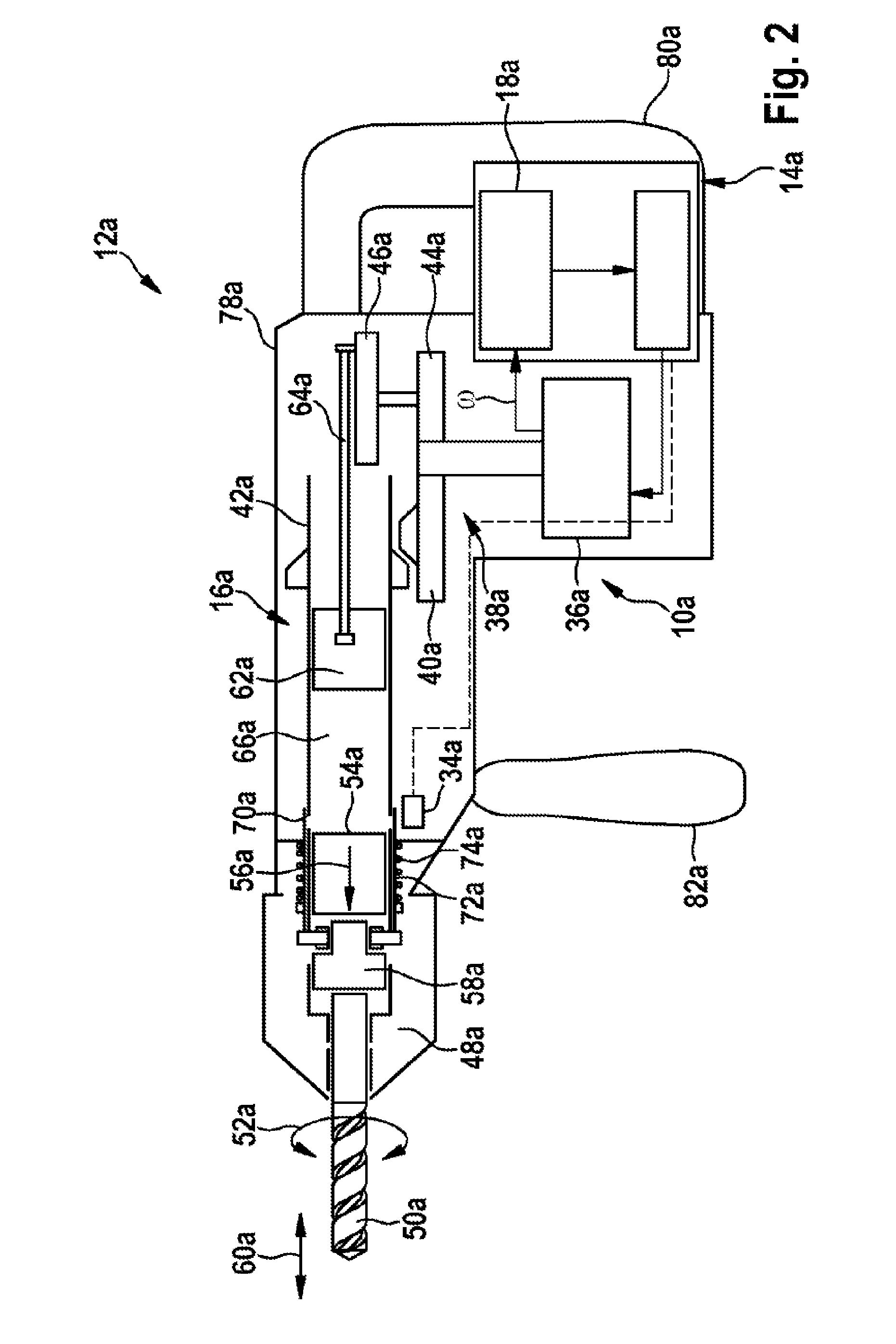
[0041]FIG. 1 and FIG. 2 show a rotary and percussion hammer 12a, having a percussion mechanism unit 10a, and having a control unit 14a, which is provided to control a pneumatic percussion mechanism 16a by open-loop and closed-loop control. The percussion mechanism unit 10a comprises a motor 36a, having a transmission unit 38a that drives a hammer tube 42a in rotation via a first gear wheel 40a and drives an eccentric gear mechanism 46a via a second gear wheel 44a. The hammer tube 42a is connected in a rotationally fixed manner to a tool holder 48a, in which a tool 50a can be clamped. For a drilling operating mode, the tool holder 48a and the tool 50a can be driven with a rotary working motion 52a, via the hammer tube 42a. If, in a percussion operating mode, a striker 54a is accelerated in a percussion direction 56a, in the direction of the tool holder 48a, upon impacting upon a striking pin 58a that is disposed between the striker 54a and the tool 50a it exerts a percussive impulse ...


PUM

PropertyMeasurementUnit
Frequencyaaaaaaaaaa
Torqueaaaaaaaaaa

Abstract

Percussion unit, especially for a rotary hammer and/or percussion hammer, comprising a control unit which is designed for controlling a pneumatic percussion mechanism. According to the disclosure, the control unit comprises at least one load estimation device.

Description

PRIOR ART[0001]There are already known percussion mechanism units, in particular for a rotary and / or percussion hammer, comprising a control unit that is provided to control a pneumatic percussion mechanism.DISCLOSURE OF THE INVENTION[0002]The invention is based on a percussion mechanism unit, in particular for a rotary and / or percussion hammer, comprising a control unit that is provided to control a pneumatic percussion mechanism.[0003]It is proposed that the control unit have at least one load estimator. A “percussion mechanism unit” in this context is to be understood to mean, in particular, a unit provided to operate a percussion mechanism. The percussion mechanism unit may have, in particular a control unit. The percussion mechanism unit may have a drive unit and / or a transmission unit, provided to drive the percussion mechanism unit. A “control unit” in this context is to be understood to mean, in particular, a device of the percussion mechanism unit that is provided to contro...

Claims


Application Information

Patent Timeline
IPC IPC(8): B25D11/06
CPCB25D11/06B25D16/006B25D11/005B25D2250/035B25D2250/131B25D2250/145B25D2250/201B25D2250/205B25D2250/221B25D2211/003B25D2211/068B25F5/00
Inventor NITSCHE, RAINERVANDAMME, ANTOINEWINKLER, THOMASSPRENGER, HELGEHAMEDOVIC, HARISFISCHER, WOLFGANGBERTSCH, CHRISTIANZAVALA, MARIO EDUARDO VEGAHOFFMANN, ULLIHENKE, THILODUESSELBERG, ACHIM
Owner ROBERT BOSCH GMBH
Why Eureka
Try Eureka