
Fin-type field effect transistor and manufacturing method thereof

a technology of field effect transistor and manufacturing method, which is applied in the direction of semiconductor devices, basic electric elements, electrical equipment, etc., can solve the problems of prior art formation of voids and growth of adjacent epitaxial layers, and achieve the effect of reducing the lateral distan

Active Publication Date: 2015-04-16
SEMICON MFG INT (SHANGHAI) CORP
View PDF4 Cites 29 Cited by
  • Summary
  • Abstract
  • Description
  • Claims
  • Application Information

AI Technical Summary

Benefits of technology

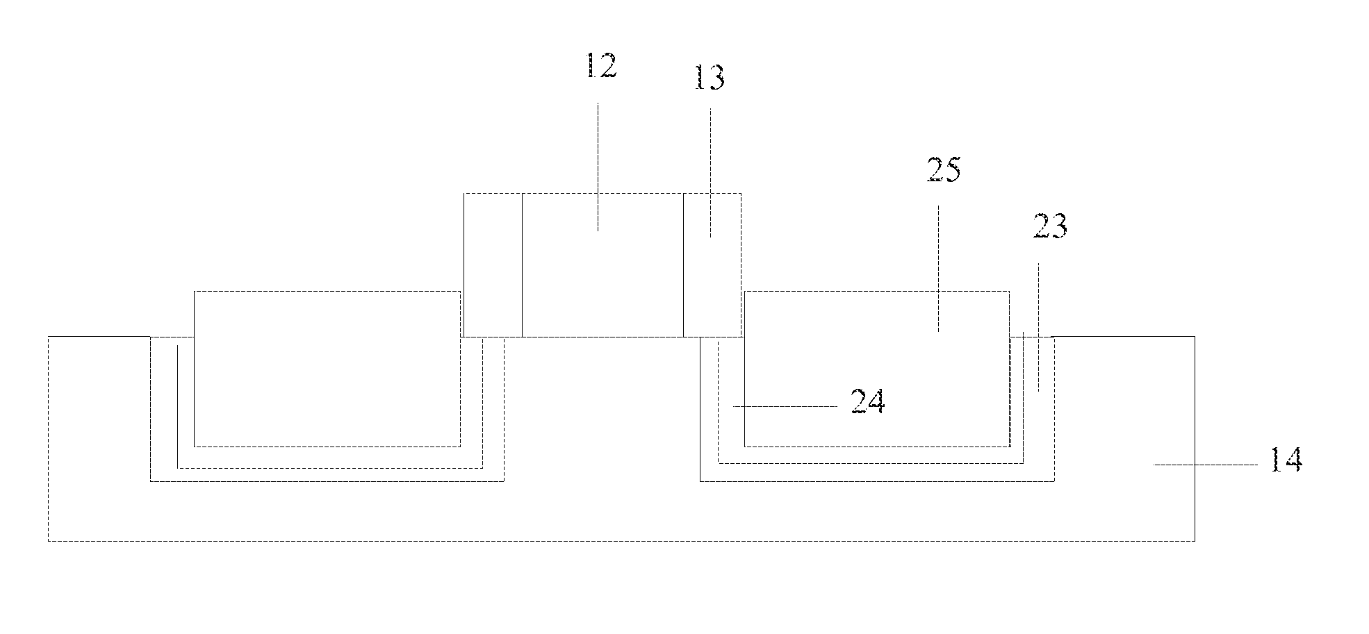
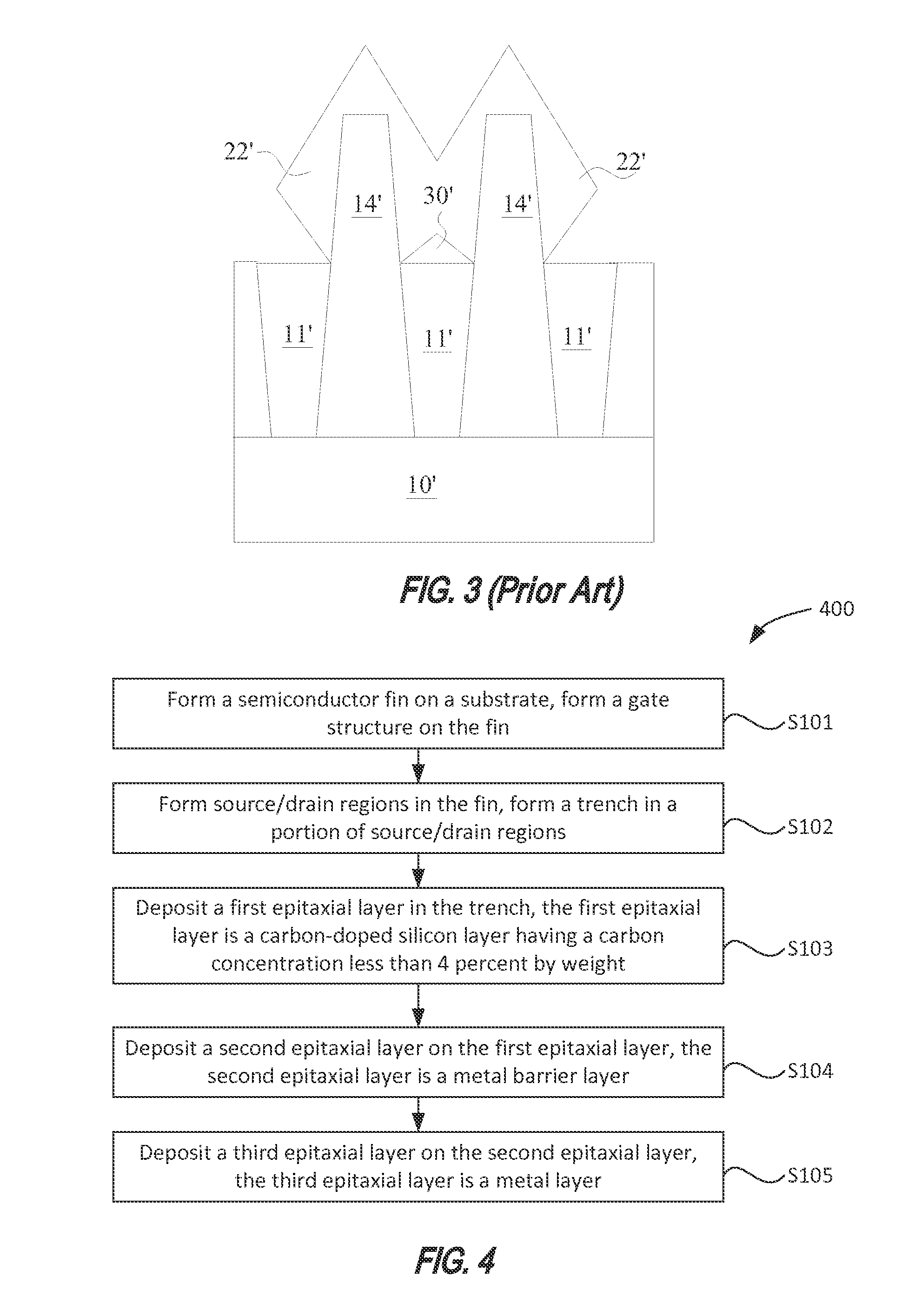
The patent text describes a new fin structure design that prevents the formation of corners on the epitaxial layers, which can reduce the air gap between adjacent layers and result in voids. The epitaxial layer is created with a trench in the source and drain regions and a barrier metal layer is placed on top, resulting in a more uniform and smooth growth process. This new design prevents the formation of corners and ensures the proper functioning of the fin structure.

Problems solved by technology

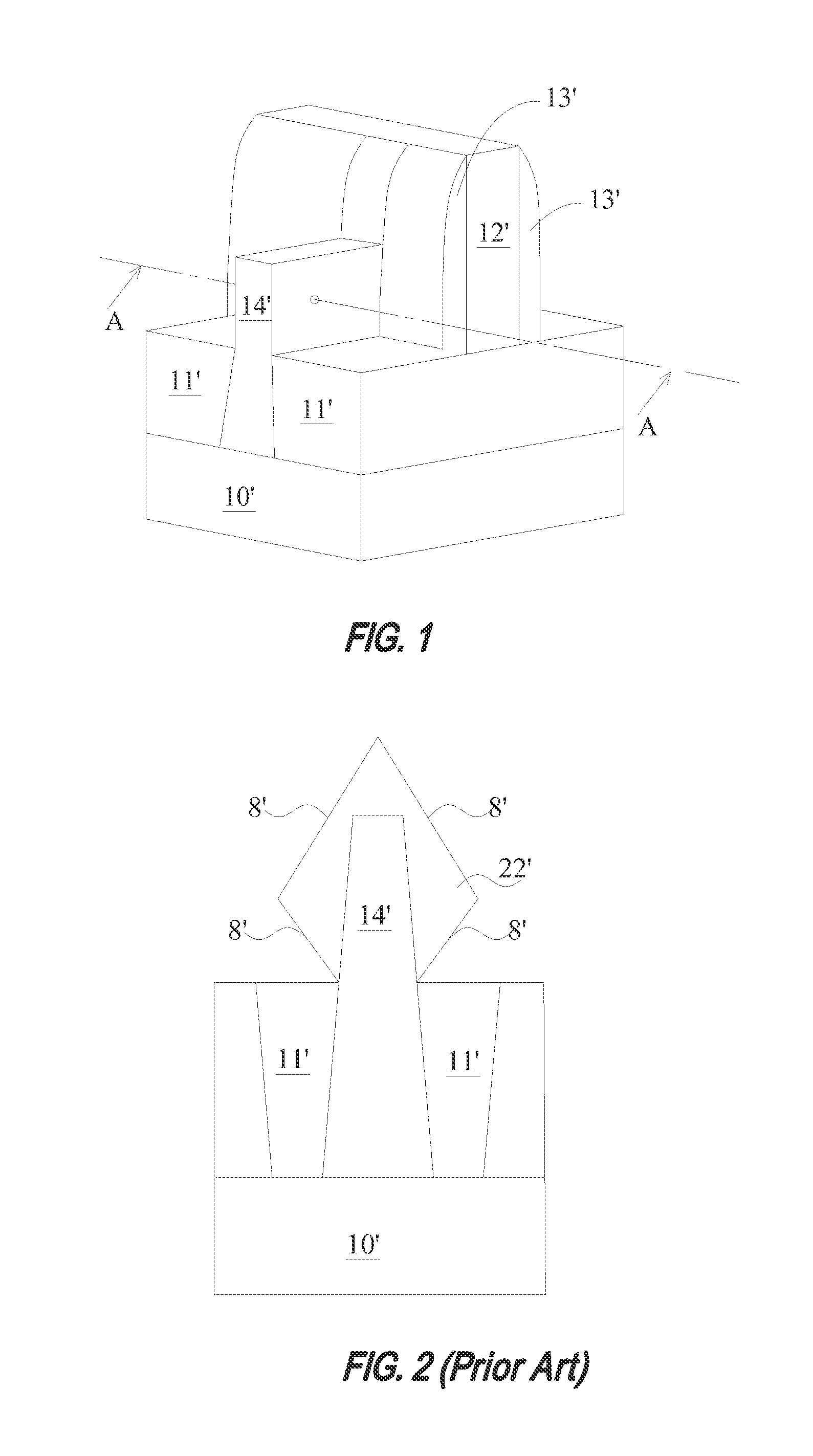
Corners formed from facets may reduce the air gap (distance) between adjacent epitaxial layers resulting in the growing together of the adjacent epitaxial layers and formation of voids in the prior art.

Method used


Image

  • Fin-type field effect transistor and manufacturing method thereof
  • Fin-type field effect transistor and manufacturing method thereof
  • Fin-type field effect transistor and manufacturing method thereof

Examples


Embodiment Construction

[0021]It should be understood that the drawings are not drawn to scale, and similar reference numbers are used for representing similar elements. As used herein, the terms “example embodiment,”“exemplary embodiment,” and “present embodiment” do not necessarily refer to a single embodiment, although it may, and various example embodiments may be readily combined and interchanged, without departing from the scope or spirit of the present invention. Furthermore, the terminology as used herein is for the purpose of describing example embodiments only and is not intended to be a limitation of the invention. In this respect, as used herein, the term “in” may include “in” and “on”, and the terms “a”, “an” and “the” may include singular and plural references. Furthermore, as used herein, the term “by” may also mean “from”, depending on the context. Furthermore, as used herein, the term “if” may also mean “when” or “upon”, depending on the context. Furthermore, as used herein, the words “and...


PUM


Abstract

A FinFET device includes a gate dielectric layer on a substrate, a fin on the gate dielectric layer having a middle section and source and drain regions at opposite ends, and a gate structure on the middle section of the fin. The FinFET device also includes a trench in a portion of the source and drain regions and a multi-layered epitaxial structure in the trench. The multi-layered epitaxial structure includes a first epitaxial layer in direct contact with the bottom of the trench, a second epitaxial layer on the first epitaxial layer, and a third epitaxial layer on the second epitaxial layer. The first epitaxial layer is a carbon-doped silicon layer having a carbon dopant concentration of less than 4 percent by weight, the second epitaxial layer is a barrier metal layer, and the third epitaxial layer is a metal layer.

Description

CROSS-REFERENCES TO RELATED APPLICATIONS[0001]This application claims priority to Chinese patent application No. 201310479801.6, filed on Oct. 14, 2013, the content of which is incorporated herein by reference in its entirety.BACKGROUND OF THE INVENTION[0002]The present invention relates to semiconductor devices, and more particularly to semiconductor devices having a fin structure and a method of manufacturing the same.[0003]As the size of semiconductor devices is steadily scaled down, the performance of semiconductor devices is continuously improved. From a structural point of view, single-gate transistors have been replaced by multi-gate transistors. Fin field-effect transistors (FinFETs) are widely used in integrated circuits for their increased gate widths over planar transistors.[0004]FIG. 1 is a perspective view of a fin field effect transistor (FinFET). As shown in FIG. 1 for illustrative purposes, the FinFET includes a semiconductor substrate 10′, a fin structure (alternati...

Claims


Application Information

Patent Timeline
Patent Type & Authority Applications(United States)
IPC IPC(8): H01L29/66H01L21/283H01L29/78
CPCH01L29/66795H01L29/785H01L21/283H01L29/7848
Inventor MIENO, FUMITAKE
Owner SEMICON MFG INT (SHANGHAI) CORP
Learn More