
Splatter shield for cooking

a technology for shields and cooking, applied in the field of splatter shields for cooking, can solve the problems of splattering grease on the surrounding cooking surface and countertop, affecting the safety of consumers, so as to prevent the steaming of food

Inactive Publication Date: 2015-04-16
JAZ INNOVATIONS
View PDF3 Cites 21 Cited by
  • Summary
  • Abstract
  • Description
  • Claims
  • Application Information

AI Technical Summary

Benefits of technology

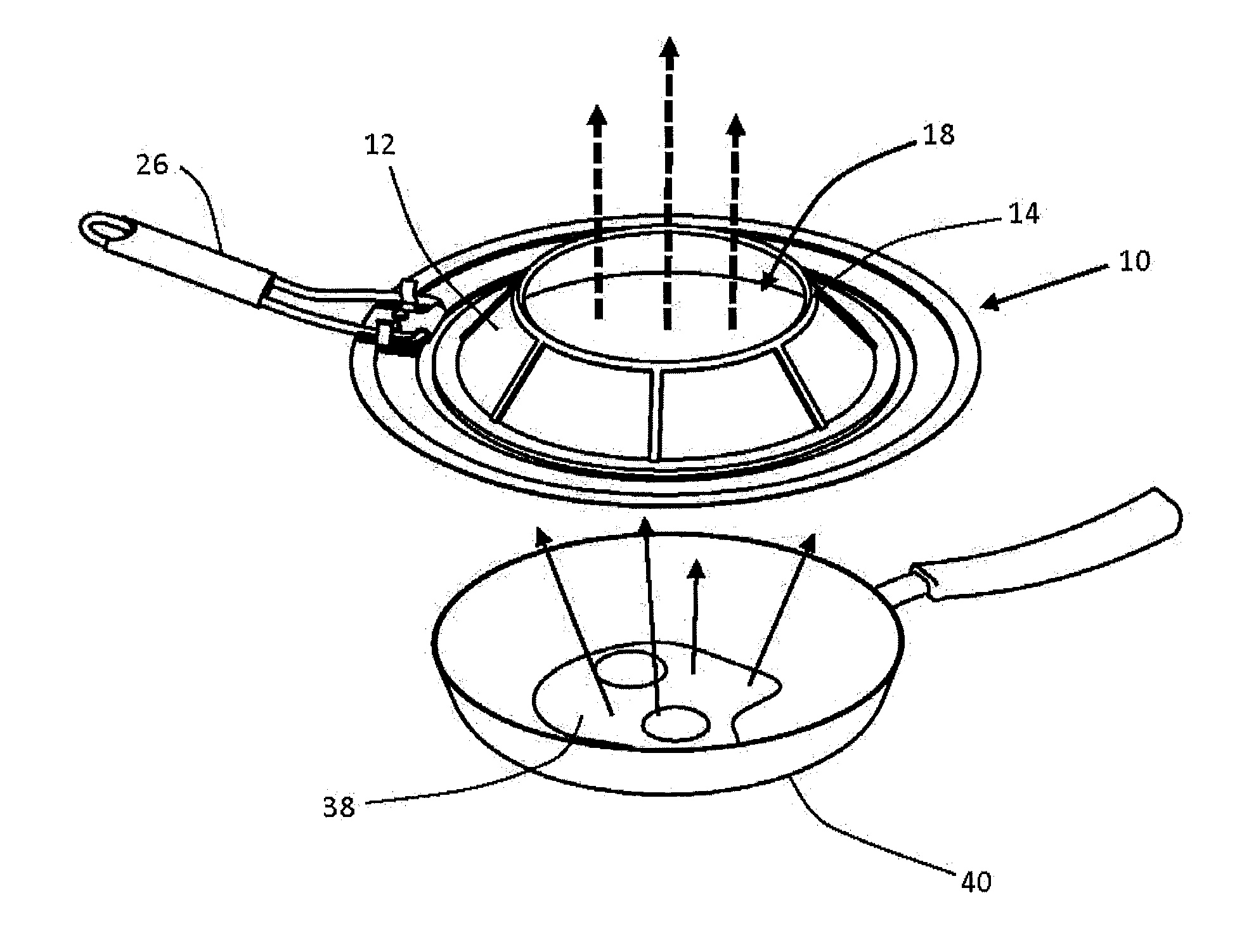
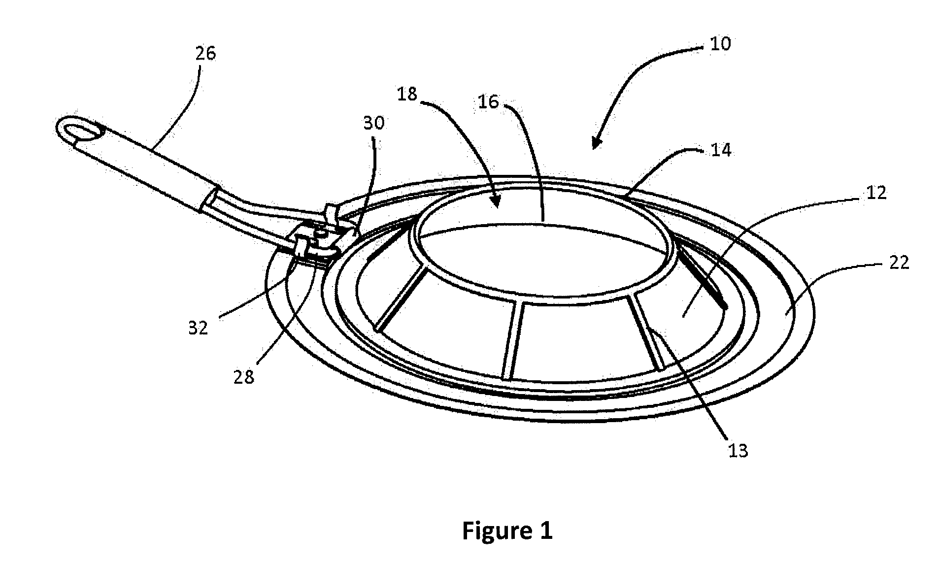
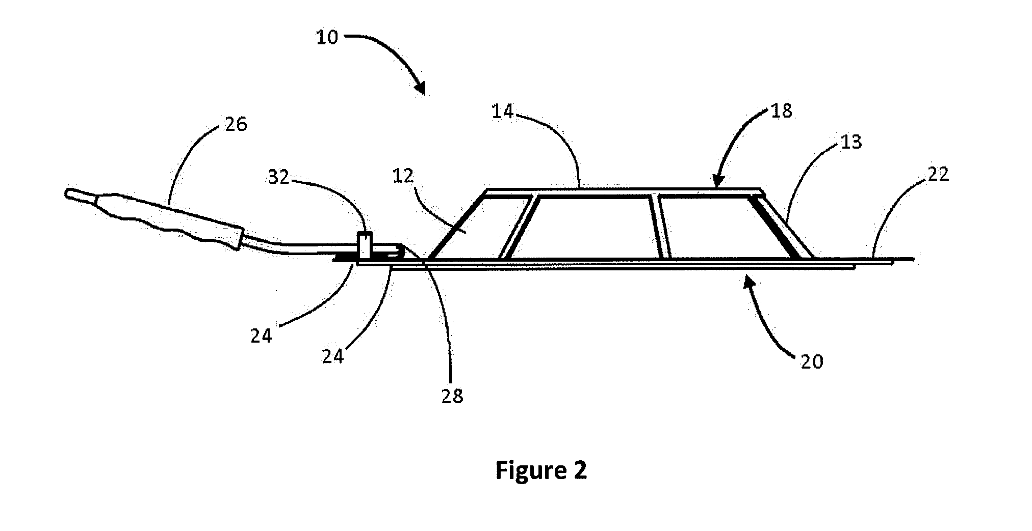
The invention provides a splatter shield with a half-domed or truncated cone configuration and having a substantially sized, central opening in its top. The walls of the splatter shield are configured to contain substantially all the grease splatter except that which goes vertically from the pan. The opening is wide enough to allow the cook easy access to the cooking food in order to turn, stir, or otherwise manipulate the food. The splatter shield sidewall is inwardly sloping, efficient trapping of grease splatters and allowing for easy manipulation of the food being cooked while preventing grease from spraying onto the stove or counter top. The central opening is sized large enough to allow the chef to easily manipulate the food being cooked while ensuring that food will fry and not steam.

Problems solved by technology

Frying foods on the stove-top invariably results in the splattering of grease on the surrounding cooking surface and countertop as the food cooks.
Splattering grease can be a significant health hazard as well as a nuisance; the hot grease can cause serious burns to skin, can stain clothing, and can necessitate lengthy clean-up procedures.
The mesh screens also importantly allow steam to escape during the cooking process; this prevents the food from steaming instead of frying, which would result in an unpalatable result.
A problem common to all the splatter shields described above is the need to lift or remove the splatter shield to stir or turn the food being cooked.
The limited access provided by this small opening is too small and at too low an angle to allow the cook to adequately turn or manipulate larger pieces of foods such as chicken or bacon; merely enlarging the opening would allow significant grease splatter to escape out the side of the splatter shield.
Grease splatters thus impact the walls of the device.
Joseph's device has several drawbacks making it an impractical device for cooking.
First, there is the need to construct the grease trapping cylinder by linking multiple individual segments together while they are resting in a frying pan or cook pot that is presumed filled with hot oil over a flame.
Second, the device shown by Joseph has high, vertical walls as these are necessary to contain the grease splatters.
Although it is possible to reach the food during the cooking process, these high vertical walls necessitate reaching almost vertically into the frying pan with an entire arm (for smaller folks), risking being burned by splattering grease.
Lastly, to remove the food after cooking, it is necessary to disconnect the individual segments at a point when they can be presumed to be greasy and extremely hot, making this a very hazardous endeavor.
No mention is made of any other manipulation of the cooking food, and the hole is far too small to allow insertion of other utensils such as tongs or spatulas.
Also, the hole is located at the apex of the cone at a significant distance from cooking food, making it virtually impossible to perform such actions as turning or flipping frying foods due to the angle and distance involved.

Method used


Image

  • Splatter shield for cooking
  • Splatter shield for cooking
  • Splatter shield for cooking

Examples


Embodiment Construction

[0026]It is to be understood that the invention may assume various alternative orientations and step sequences, except where expressly specified to the contrary. It is also to be understood that the specific devices and processes illustrated in the attached drawings, and described in the following specification are simply exemplary embodiments of the inventive concepts defined in the appended claims. Hence, specific dimensions, directions or other physical characteristics relating to the embodiments disclosed are not to be considered as limiting, unless the claims expressly state otherwise.

[0027]The splatter shield of the invention is formed with a half-domed or truncated cone configuration and includes a substantially sized, central opening in its top. The walls of this splatter shield are configured to contain substantially all the grease splatter except that which goes vertically from the pan. The opening is sufficiently large to allow the cook easy access to the cooking food in ...


PUM


Abstract

A splatter shield is provided for controlling grease splatter from food being cooked within a cooking vessel. The splatter shield includes a generally annular sidewall that slopes upwardly and radially inwardly from a lower rim to an upper rim. The upper rim of the splatter shield defines an upper opening in the splatter shield that is sufficiently large to permit the introduction of a cooking utensil therethrough, and the lower rim defines a lower opening in the splash shield. The upper opening in the splatter shield is smaller than the lower opening.

Description

CROSS-REFERENCE TO RELATED APPLICATION[0001]This application is claiming the benefit, under 35 U.S.C. §119(e), of the provisional application filed Oct. 11, 2013 under 35 U.S.C. §111(b), which was granted Ser. No. 61 / 889,567. The noted provisional application is hereby incorporated by reference in its entirety.BACKGROUND OF THE INVENTION[0002]Frying foods on the stove-top invariably results in the splattering of grease on the surrounding cooking surface and countertop as the food cooks. This results from the interaction of hot grease with water and water-based components of the food being fried. Splattering grease can be a significant health hazard as well as a nuisance; the hot grease can cause serious burns to skin, can stain clothing, and can necessitate lengthy clean-up procedures.[0003]Splatter shields (also known and referenced as splatter screens, spatter screens, and spatter guards) have been developed and used for years to address this problem. In their most common form, sp...

Claims


Application Information

Patent Timeline
Patent Type & Authority Applications(United States)
IPC IPC(8): A47J37/10A23L1/01A23L5/10
CPCA47J37/101A23L1/0107A23V2002/00A47J36/064A23L5/10A47J37/108
Inventor HUTTNER, JAMES J.
Owner JAZ INNOVATIONS
Learn More