System for camera-based vital sign measurement

Inactive Publication Date: 2015-04-16
KONINKLJIJKE PHILIPS NV
View PDF5 Cites 49 Cited by
  • Summary
  • Abstract
  • Description
  • Claims
  • Application Information

AI Technical Summary

Benefits of technology

[0005]It is an object of the present invention to provide a system, device and met

Problems solved by technology

In particular, a manual selection of the ROI is time-consuming.
Further, moveme

Method used


Image

  • System for camera-based vital sign measurement
  • System for camera-based vital sign measurement
  • System for camera-based vital sign measurement

Examples


Embodiment Construction

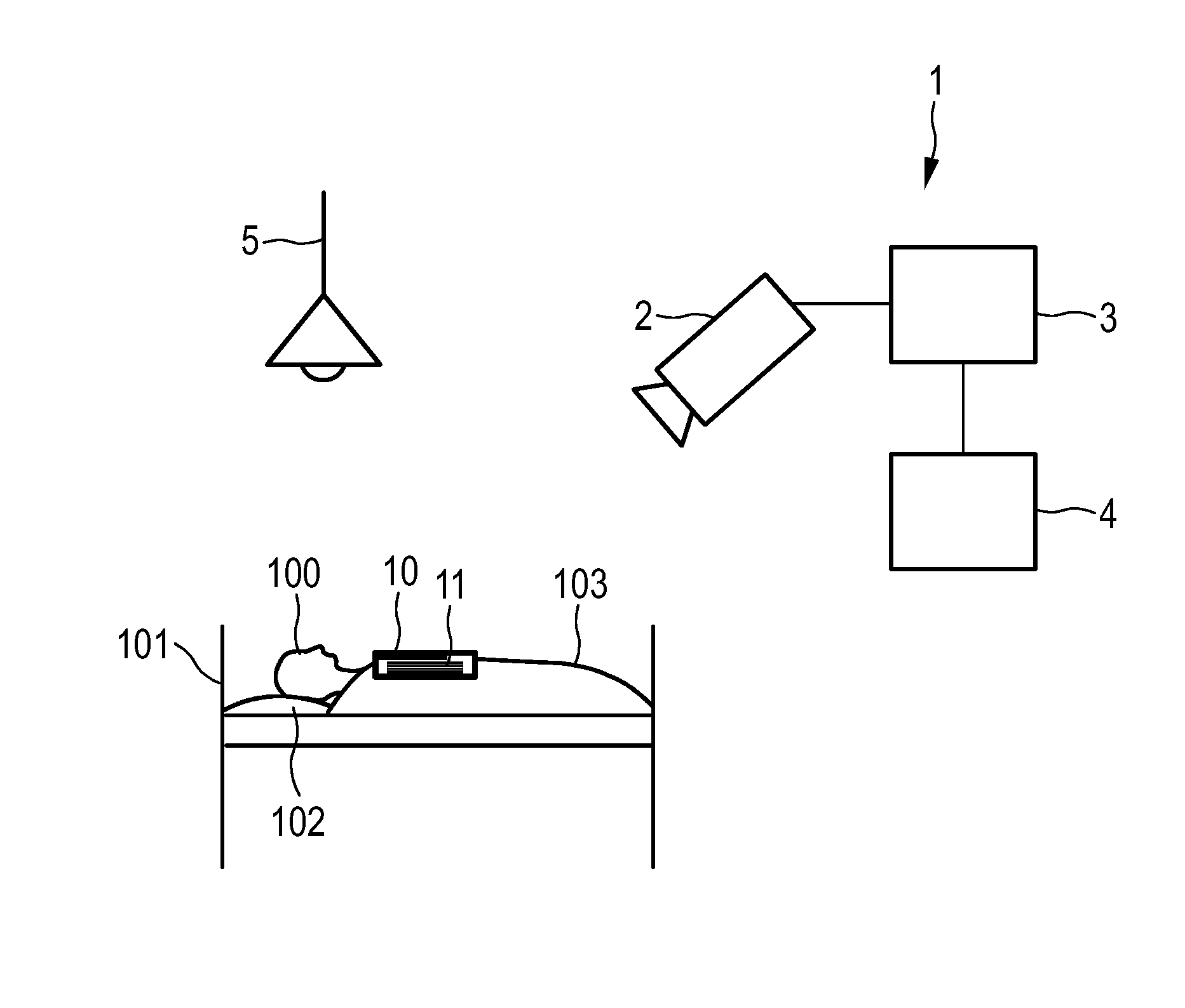
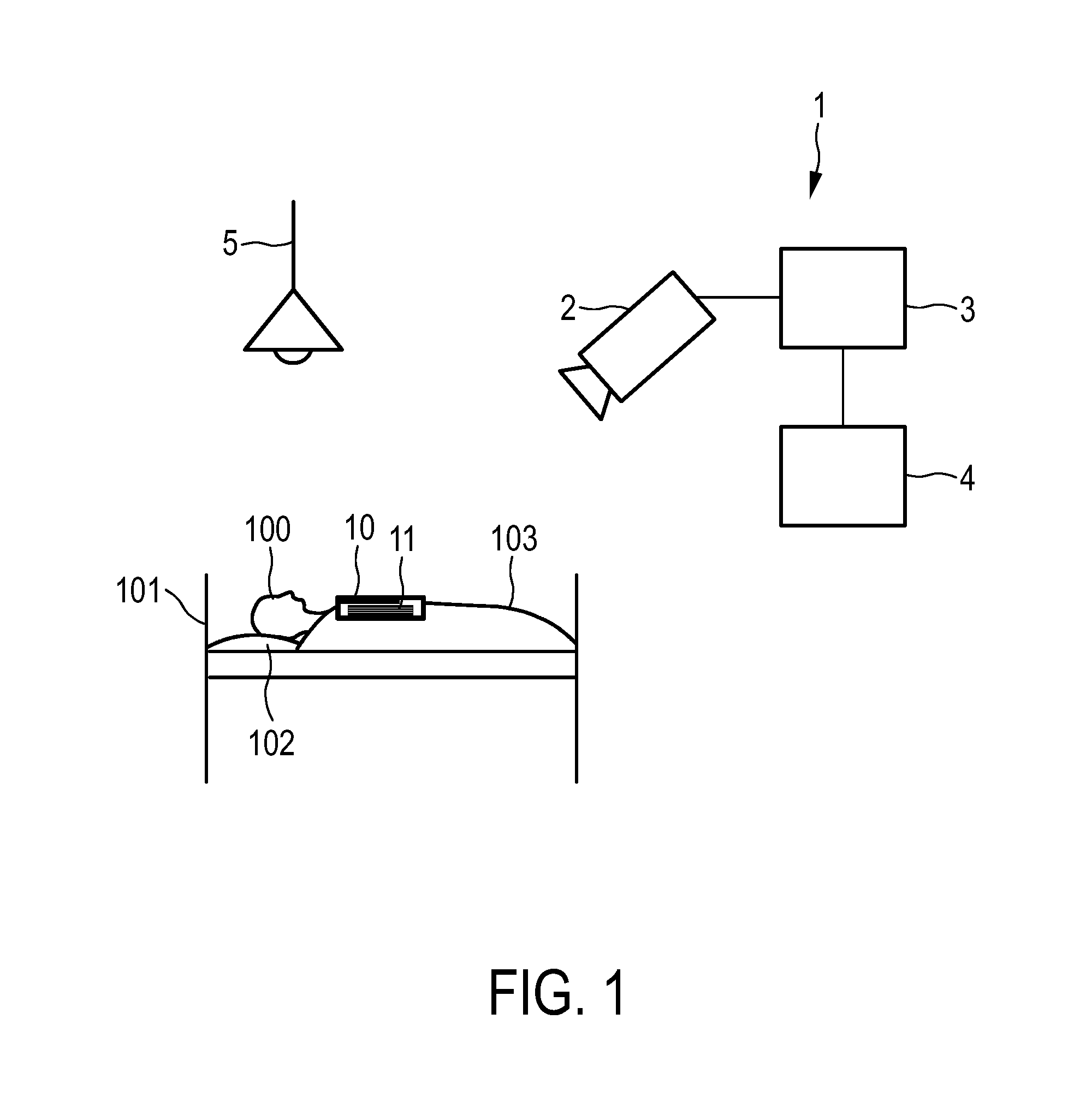
[0054]FIG. 1 shows an exemplary embodiment of a system 1 for determining a vital sign of a subject 100 according to the present invention. The subject 100 lies in a bed 101, wherein the head of the subject 100 is located on a pillow 102 and the subject 100 is covered with a blanket 103. The system 1 comprises an imaging unit 2 for obtaining video data of the subject 100 and a marker 10 attached to a body of the subject 100. The marker 10 comprises a graphical pattern 11. An image processing unit 3 is adapted to detect said marker 10 in the video data. An analysis unit 4 is adapted to extract a vital sign parameter related to a vital sign of the subject 100 from the video data and to determine a vital sign from the vital sign parameter. In this example, the vital sign parameter is a respiratory movement and the vital sign is a respiratory rate.

[0055]The marker 10 is directly attached to the body of the subject 100 by placing it on the chest of the subject 100. In this example, the ma...


PUM


Abstract

The present invention relates to the measurement of vital signs such as a respiratory rate or a heart rate. In particular, a system (1) for determining a vital sign of a subject (100), comprising an imaging unit (2) for obtaining video data of the subject, a marker (10, 20, 60, 61) directly or indirectly attached to a body of the subject, wherein the marker comprises a graphical pattern (11, 21), an image processing unit (3) for detecting said marker in said video data, and an analysis unit (4) adapted to extract a vital sign parameter related to the vital sign of the subject from said video data and to determine the vital sign from said vital sign parameter. Further aspects of the invention relate to a device and a method for determining a vital sign of a subject and a computer program for carrying out said method.

Description

FIELD OF THE INVENTION[0001]The present invention relates to a system, device, method and computer program for determining a vital sign, in particular a respiratory rate, of a subject.BACKGROUND OF THE INVENTION[0002]Vital signs of a person, for example the heart rate (HR) or respiratory rate (RR), can serve as a powerful predictor of serious medical events. For this reason, the respiratory rate is often monitored online in intensive care units or in daily spot checks in the general ward of a hospital. A non-invasive respiratory rate measurement can be accomplished optically with the help of a stationary video camera.[0003]A video camera captures the breathing movements of a patient's chest in a stream of images. The breathing movements lead to a temporal modulation of certain image features, wherein the frequency of the modulation corresponds to the respiratory rate. Examples of such image features are the average amplitude in a spatial region of interest (ROI) around the patient's...

Claims


Application Information

Patent Timeline
IPC IPC(8): A61B19/00A61B5/00A61B5/024A61B5/08
CPCA61B19/54A61B5/0816A61B5/441A61B5/02427A61B5/7278A61B2019/5437A61B5/0077A61B5/02416A61B5/1127A61B5/113A61B5/117A61B5/7207A61B2090/3937A61B90/39
Inventor BRESCH, ERIKMUEHLSTEFF, JENSTIGGES, TIMODUBIELCZYK, ALEXANDERSHAN, CAIFENG
Owner KONINKLJIJKE PHILIPS NV
Why Eureka
Try Eureka