
Method for knee resection alignment approximation in knee replacement procedures

a knee resection and alignment technology, applied in the field of knee resection alignment approximation in knee replacement procedures, can solve the problems of reducing or wearing away, affecting the mobility of the joint,

Inactive Publication Date: 2015-04-16
UNIK ORTHOPEDICS INC
View PDF1 Cites 8 Cited by
  • Summary
  • Abstract
  • Description
  • Claims
  • Application Information

AI Technical Summary

Benefits of technology

The patent describes systems and methods for processing medical scans of a patient's anatomy, specifically focusing on the hip and knee joints. The technology uses image analysis to extract information from the scan and create a virtual model of the bones and cartilage. This virtual model is then used to determine the optimal position for a cutting guide or reference point during a surgical procedure. The system and method can provide accurate and reliable information to surgeons, improving the precision and accuracy of the surgery. The technology also allows for the efficient and accurate customization of cutting guides for individual patients.

Problems solved by technology

Through over-use, traumatic events and / or debilitating disease, a person's joint may become damaged to the point that the joint is repaired.
Damage to the joint may result in a reduction or wearing away of cartilage in the joint area, which operates to provide frictional, compressive, shear, and tensile cushioning within the joint.
As such, reduction in cartilage in a joint causes pain and decreased mobility of the joint.

Method used


Image

  • Method for knee resection alignment approximation in knee replacement procedures
  • Method for knee resection alignment approximation in knee replacement procedures
  • Method for knee resection alignment approximation in knee replacement procedures

Examples


Embodiment Construction

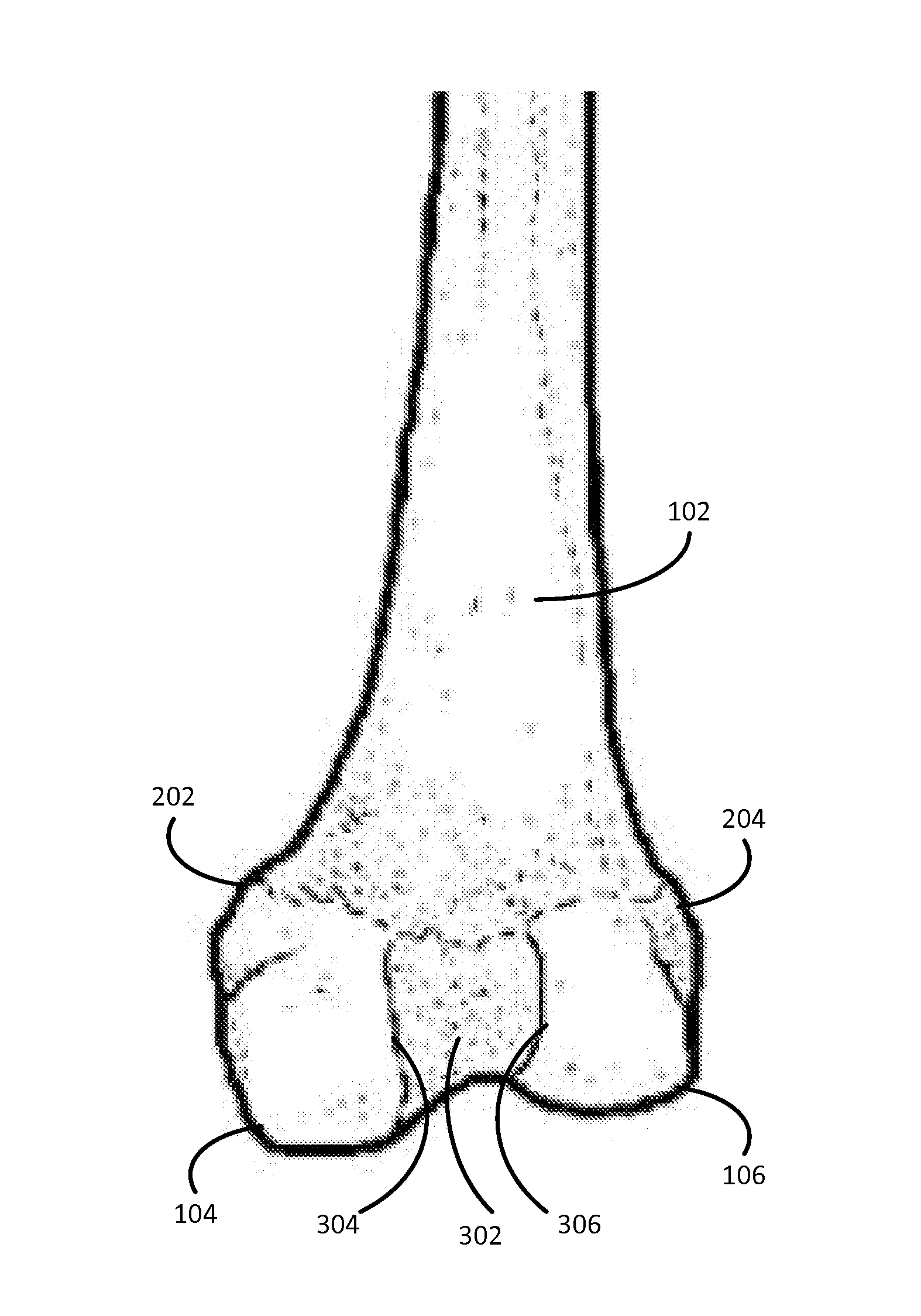
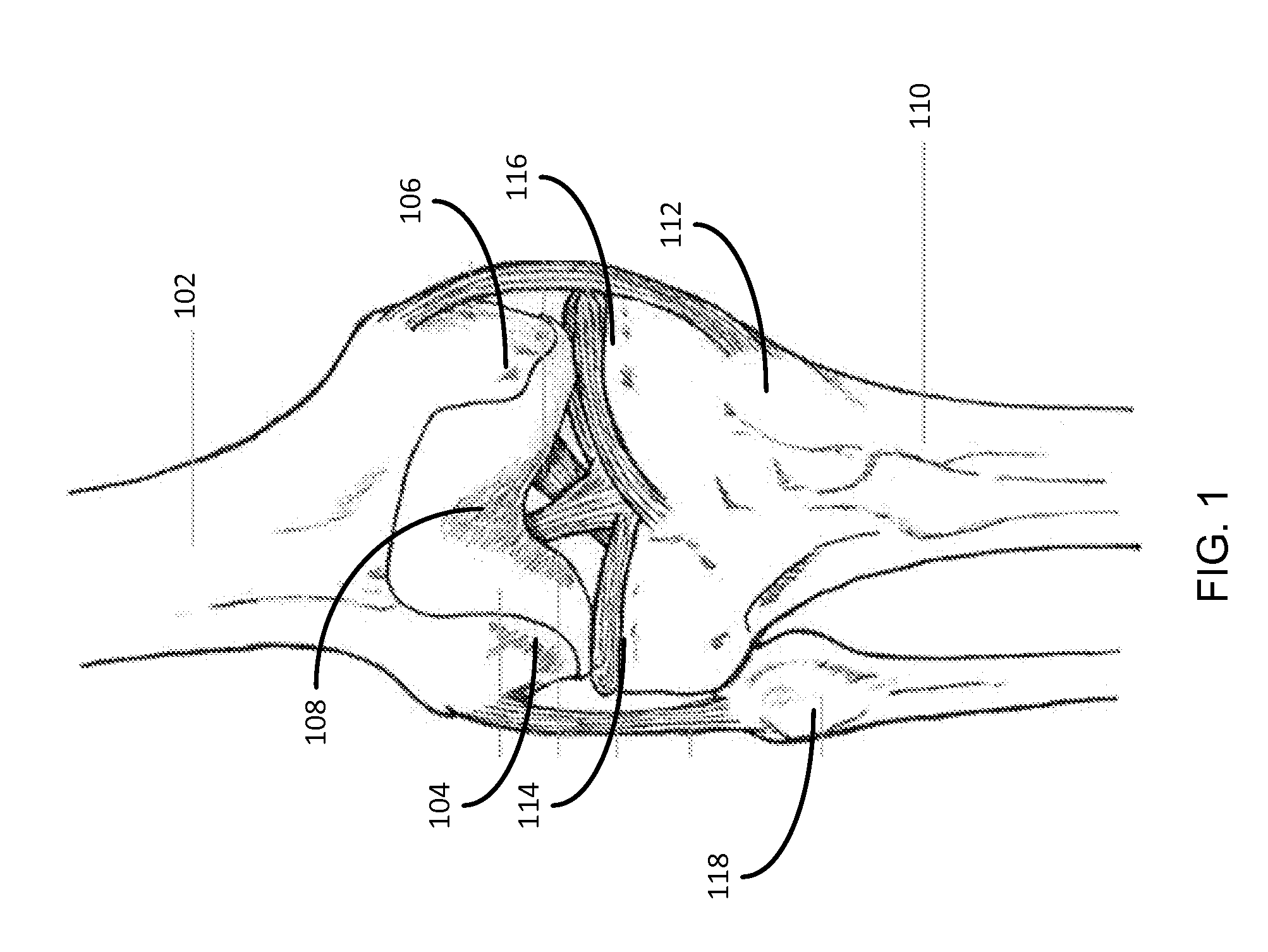
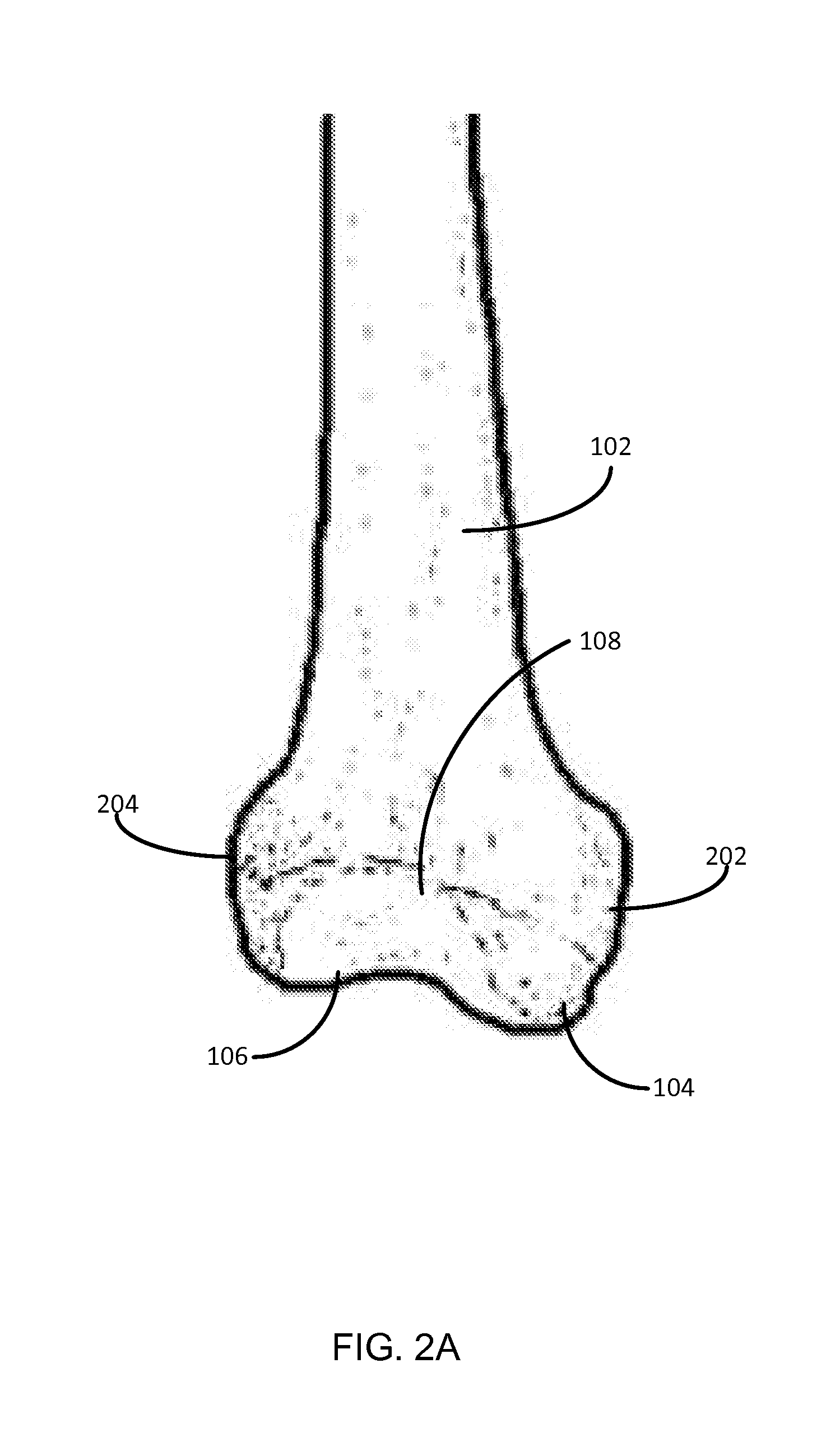
[0029]Aspects of the present disclosure involve systems, methods, computer program products, manufacture process and the like, for utilizing a series of images of a patient's anatomy to determine a cut plane for use during a knee procedure. In particular, the present disclosure provides for a method of utilizing one or more two-dimensional (2D) images of the patient's joint to undergo an arthroplasty procedure. The method includes receiving the 2D images of the joint from an imaging device and determining the location within at least one of the 2D images of the patient's cortical bone edge. In general, the location of the cortical bone edge of the patient's knee is determined by analyzing the gray scale value of one or more pixels around a selected point on the image. In particular, a range of pixels around the selected point provides a range of gray scale values that may be analyzed to determine the pixel with the lowest gray scale value. This pixel may then be assumed to be the ed...


PUM


Abstract

Aspects of the present disclosure involve systems, methods, computer program products, and the like, for utilizing a series of images of a patient's anatomy to determine a cut plane for use during a knee procedure. To determine a cut plane for use during a knee replacement procedure, the 2D images may be analyzed by a computer program to determine a femoral shaft axis reference line, a center of rotation of the knee, and the valley floor of the condyle notch. With these landmarks identified in the images, a cut plane through the femur for use during a TKA procedure may be determined. Further, the location of these features in the images may be determined by analyzing the gray scale value of one or more pixels around a selected point on the image. The pixel with the lowest gray scale value may then be assumed to be the edge of the cortical bone in the 2D image.

Description

CROSS-REFERENCE TO RELATED APPLICATIONS[0001]This application claims priority under 35 U.S.C. §119(e) to U.S. Provisional Application No. 61 / 961,541 entitled “IMPROVEMENTS IN KNEE FEMUR REPLACEMENT AND ALIGNMENT”, filed on Oct. 16, 2013 which is incorporated by reference in its entirety herein.TECHNICAL FIELD[0002]Aspects of the present disclosure generally relate to systems and methods for an accurate determination of relevant dimensions and alignments (lengths, angles, etc.) associated with a procedure for partial or total replacement of a knee component of a patient. Additional aspects of the present disclosure generally relate to systems and methods for identifying a cortical bone edge in a two-dimensional image of a knee component of a patient.BACKGROUND[0003]Through over-use, traumatic events and / or debilitating disease, a person's joint may become damaged to the point that the joint is repaired. One type of procedure to address damage to a person's joint is an arthroplasty pr...

Claims


Application Information

Patent Timeline
IPC IPC(8): A61B17/17G06T7/00A61B5/107A61B5/055A61B5/11
CPCA61B17/1703A61B5/055A61B5/1121A61B5/1079G06T7/0044G06T7/0085G06T7/0097G06T2207/20101G06T2207/30008G06T2207/10088A61B5/4571A61B5/4585G06T2207/20168A61B17/155G06T7/12
Inventor PARK, ILWHAN
Owner UNIK ORTHOPEDICS INC
Learn More