Cooling Device for Internal Combustion Engine and Failure Diagnosis Method for Cooling Device for Internal Combustion Engine

a cooling device and internal combustion engine technology, applied in the direction of machines/engines, mechanical equipment, instruments, etc., can solve the problems of lowering the accuracy of failure diagnosis, leakage flow rate in the cooling passage, and open failure of the thermostat valve, so as to prevent misdiagnosis and improve the accuracy of failure detection

a cooling device and internal combustion engine technology, applied in the direction of machines/engines, mechanical equipment, instruments, etc., can solve the problems of lowering the accuracy of failure diagnosis, leakage flow rate in the cooling passage, and open failure of the thermostat valve, so as to prevent misdiagnosis and improve the accuracy of failure detection

US20150107345A1Active Publication Date: 2015-04-23TOYOTA JIDOSHA KK

Image

  • Cooling Device for Internal Combustion Engine and Failure Diagnosis Method for Cooling Device for Internal Combustion Engine
  • Cooling Device for Internal Combustion Engine and Failure Diagnosis Method for Cooling Device for Internal Combustion Engine
  • Cooling Device for Internal Combustion Engine and Failure Diagnosis Method for Cooling Device for Internal Combustion Engine

Examples


modified example

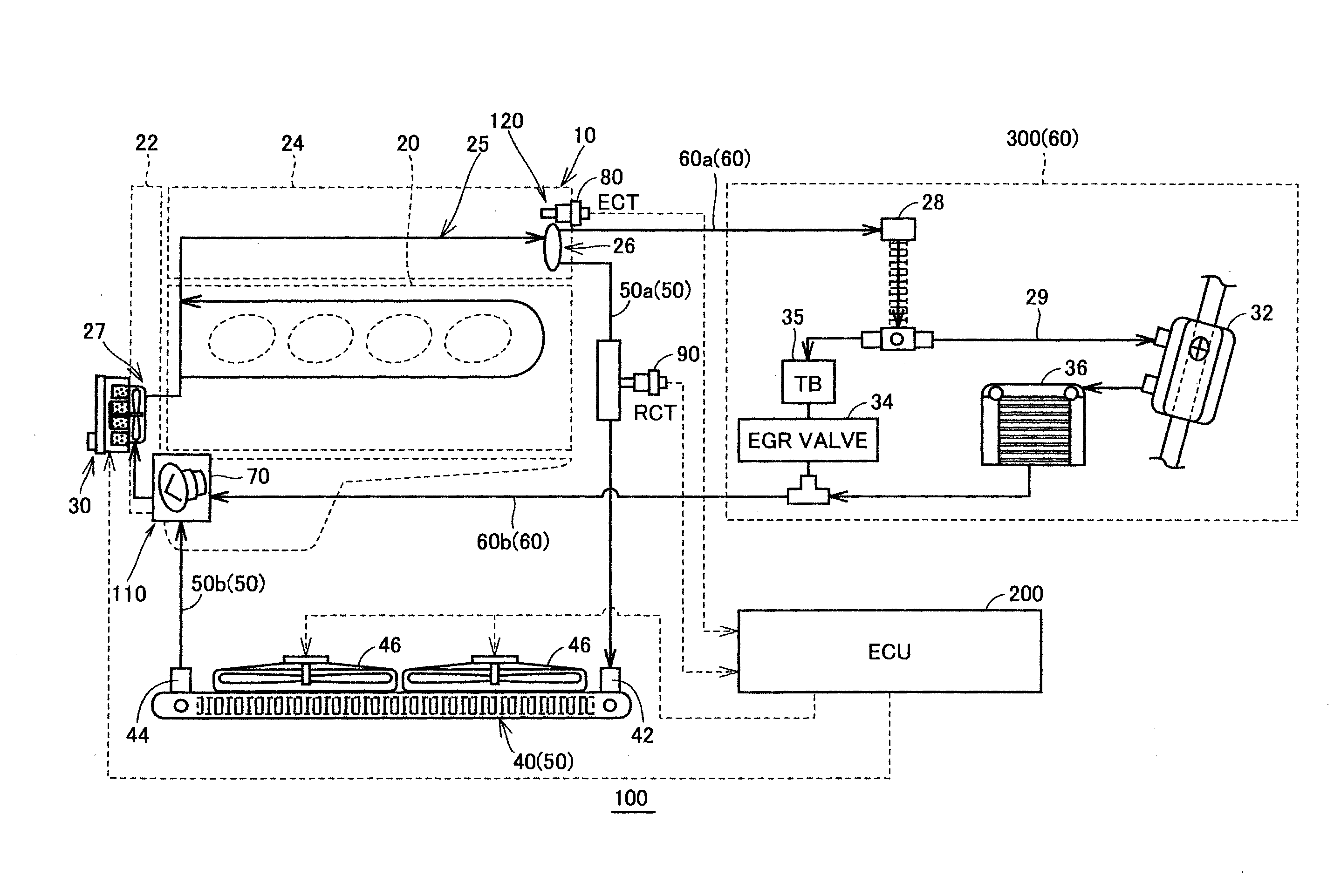
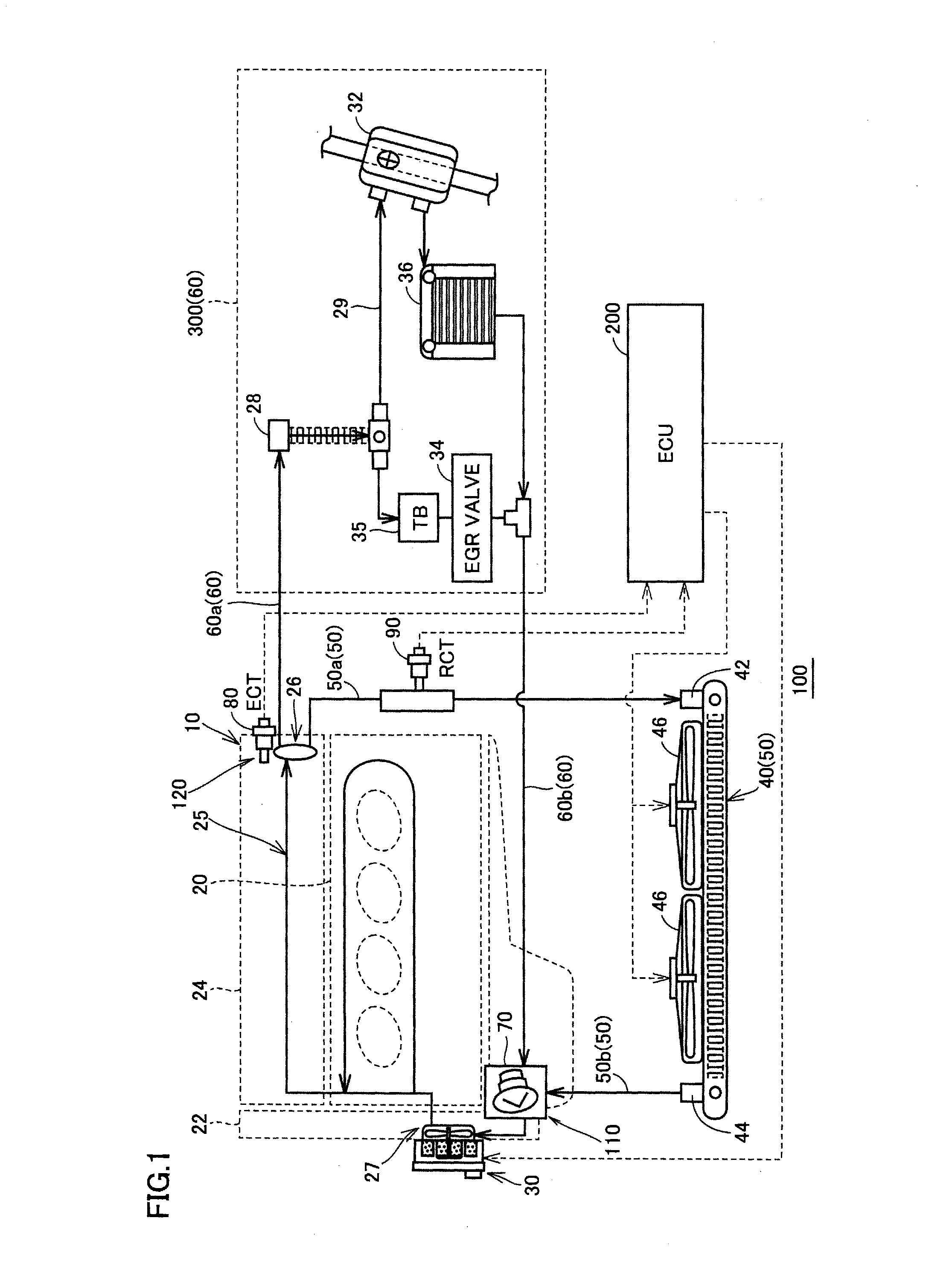
[0079]FIG. 4 represents an example of a configuration of the bypass passage shown in FIG. 1. FIG. 5 represents an example of a configuration of the bypass passage according to a modified example of the embodiment of the present invention.

[0080]Referring to FIGS. 4 and 5, in the present embodiment, the case was described in which radiator circulation passage 50 and bypass passage 60 are branched at outlet 26. In the modified example of the embodiment, the case will be described in which bypass passage 60A is branched out from radiator circulation passage 50 at a branch point P between outlet 26A and radiator-side coolant water temperature sensor 90. It should be noted that other configuration of outlet 26A and bypass passage 60A according to the modified example of the embodiment is the same as the embodiment.

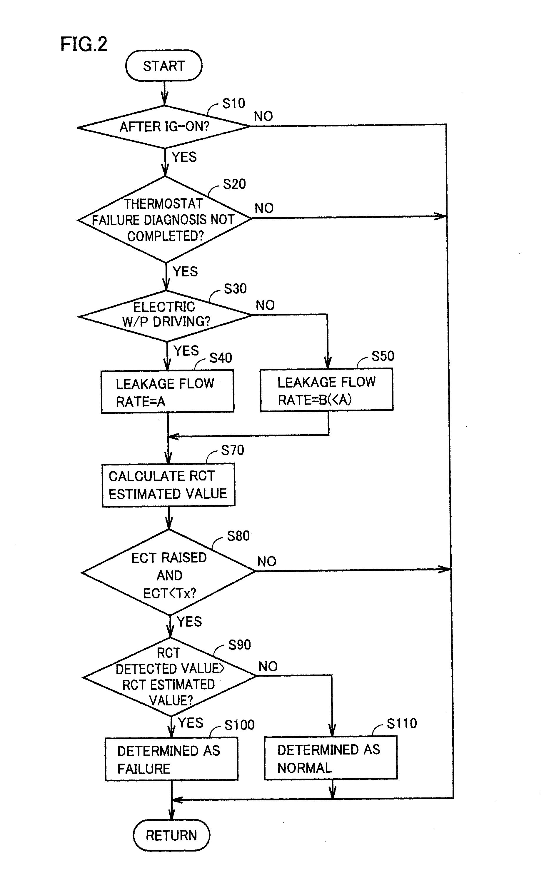
[0081]In the modified example of the embodiment, the calculation method for the RCT estimated value is different from that of the embodiment. Specifically, the temperature varia...


PUM


Abstract

An ECU sets a leakage flow rate flowing through a radiator circulation passage in a closed state of a thermostat valve, calculates an estimated temperature of coolant water in the radiator circulation passage based on a set leakage flow rate and a detected water temperature of an engine-side coolant water temperature sensor, and performs a failure diagnosis for the thermostat valve based on a difference between the calculated estimated temperature and the detected water temperature of the radiator-side coolant water temperature sensor. The leakage flow rate during operation of the electric pump is set to be a larger value as compared to the leakage flow rate during stopping of the pump. As a result, a diagnostic can be prevented by improving an accuracy of failure detection for the thermostat valve.

Description

[0001]This nonprovisional application is based on Japanese Patent Application No. 2013-216237 filed on Oct. 17, 2013 and No. 2014-188364 filed on Sep. 17, 2014 with the Japan Patent Office, the entire contents of which are hereby incorporated by reference.BACKGROUND OF THE INVENTION[0002]1. Field of the Invention[0003]The present invention relates to a cooling device for an internal combustion engine, and a failure diagnosis method for a cooling device for an internal combustion engine. More particularly, it relates to a cooling device for an internal combustion engine having a failure diagnosis function for a thermostat valve and a failure diagnosis method for the cooling device of an internal combustion engine.[0004]2. Description of the Background Art[0005]Japanese Patent Laying-Open No. 2007-056722 discloses a cooling device for an internal combustion engine, in which a cooling passage connecting an engine coolant water passage provided in the engine to a radiator is disposed, a...

Claims


Application Information

Patent Timeline
23 Apr 2015
Publication
US20150107345A1
IPC
F01P11/16; F01P11/18; F01P7/16
CPC
F01P11/16; F01P7/16; F01P2031/18; F01P2023/08; F01P2025/32; F01P11/18; F01P2031/00
Inventors
SUGIMOTO, HITOKI; SASAKI, TOSHITAKE