Method for detecting and identifying a receiver in an inductive power transfer system

a technology of inductive power transfer and receiver, applied in the direction of instruments, inductances, current/voltage indication, etc., can solve the problems of undesired energy loss, inefficient power transfer, and inducible current (and therefore heat)

Active Publication Date: 2015-04-23
APPLE INC
View PDF1 Cites 13 Cited by
  • Summary
  • Abstract
  • Description
  • Claims
  • Application Information

AI Technical Summary

Problems solved by technology

A common problem with IPT systems is controlling when the transmitter should be powered and when the transmitter should be switched off.
A further problem arises when a non-receiver is brought into the range of the transmitter, and an unwanted current (and therefore heat) is induced therein.
Attempting to transfer power to non-compatible receivers may result in inefficient power transfer (thus, undesired energy loss), or transmitter and/or receiver failure.
Though this provides a means for controlling when the transmitter should be powered, it undermines the convenience that is a goal of many IPT systems.
It also requires a user to manually switch off the transmitter when the receiver is removed and does not accommodate any

Method used


Image

  • Method for detecting and identifying a receiver in an inductive power transfer system
  • Method for detecting and identifying a receiver in an inductive power transfer system
  • Method for detecting and identifying a receiver in an inductive power transfer system

Examples


Embodiment Construction

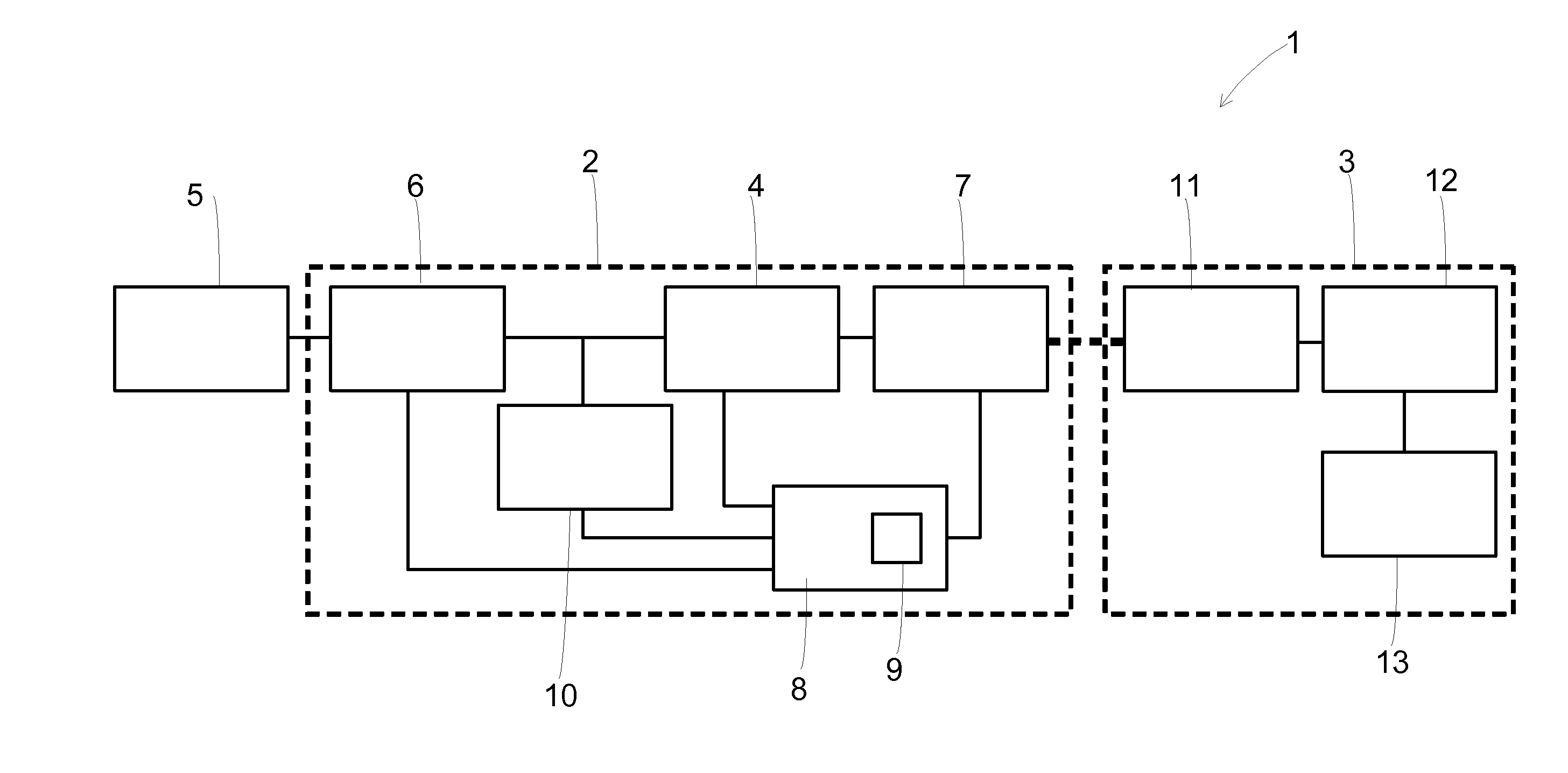
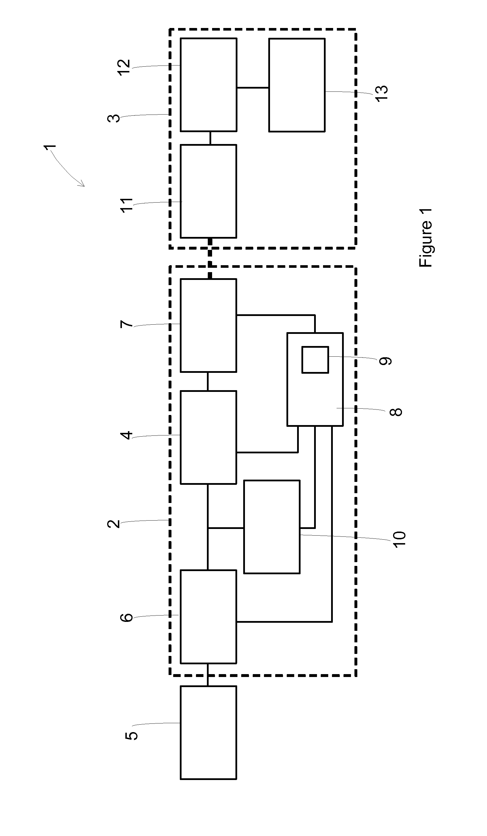
[0023]Embodiments of the present invention relate to methods for detecting or identifying a receiver in an inductive power transfer (IPT) system. FIG. 1 is a block diagram showing a general representation of an IPT system 1. The IPT system includes a transmitter 2 and a receiver 3. The transmitter includes a converter 4 that is connected to an appropriate power supply 5. In FIG. 1 this is shown as a converter that is connected to a DC-DC converter 6 that is in turn connected to the mains power supply. The converter may be a non-resonant half bridge converter or any other converter adapted for the particular IPT system, such as a push-pull converter. The converter is configured to output an alternating current of desired frequency and amplitude. The voltage of the output of the converter may also be regulated by the converter, the DC-DC converter or combination of both.

[0024]The converter 4 is connected to transmitting inductor(s) 7. The converter supplies the transmitting inductor(s...


PUM


Abstract

A method for detecting the presence of a receiver in an inductively coupled power transfer system having a transmitter and receiver. The method includes switching on a transmitter converter at a first frequency, measuring the inrush current and determining whether there is a receiver present. In another method, the inrush current is measured for a range of transmitter frequencies, and the variation in current is used to determine where there is a receiver present. In another method, the inrush current is measured when there is a change in voltage in the transmitter, and the variation in current is used to determine where there is a receiver present. In another method, the current supplied to the transmitter converter is measured over two transmitter frequencies, and the variation in current is used to determine where there is a receiver present. In another method, the current supplied to the transmitter converter is measured over two transmitter voltages, and the variation in current is used to determine where there is a receiver present.

Description

FIELD OF THE INVENTION[0001]The present invention is in the field of inductive power transfer (IPT) system. More particularly, the invention relates to methods for detecting the presence of a receiver, and or identifying a receiver, to be utilised in such systems.BACKGROUND OF THE INVENTION[0002]IPT systems are a well known area of established technology (for example, wireless charging of electric toothbrushes) and developing technology (for example, wireless charging of handheld devices on a ‘charging mat’). Typically, a primary side or transmitter generates a time-varying magnetic field with a transmitting coil or coils. This magnetic field induces an alternating current in a suitable receiving coil that can then be used to charge a battery, or power a device or other load. In some instances, the transmitter coils or the receiver coils may be connected with capacitors to create a resonant circuit, which can increase power throughput and efficiency at the corresponding resonant fre...

Claims


Application Information

Patent Timeline
IPC IPC(8): G01R27/26H02J5/00
CPCH02J5/005G01R27/2611H02J50/10H02J50/12H02J50/60H02J50/90G01R19/04G01R19/15
Inventor ROBERTSON, DANIEL JAMES
Owner APPLE INC
Why Eureka
Try Eureka