
Method and Apparatus for Recognizing a Manipulation on an Electrical Line

a technology of manipulation and electrical lines, applied in the direction of resistance/reactance/impedence, capacitance measurement, instruments, etc., can solve the problems of high manufacturing cost, uninterruptible power supply battery, and equipment to be protected, etc., to facilitate automatic recognition of changes and simple and inexpensive mechanism

Inactive Publication Date: 2015-04-23
SIEMENS AG
View PDF6 Cites 15 Cited by
  • Summary
  • Abstract
  • Description
  • Claims
  • Application Information

AI Technical Summary

Benefits of technology

The present embodiments provide a simple and inexpensive way to detect manipulations on electrical lines. The method can automatically recognize changes in the electrical line and components connected to it, and can react to those changes in a timely manner to protect the protected items. The technique can be used in a variety of applications and does not require packaging of the electrical line. Temperature compensation can be implemented to reduce false alarms caused by temperature variations.

Problems solved by technology

The equipment to be protected may not be able to perform the check automatically.
However, these technologies may protect only against accidentally occurring errors and, therefore, may be relevant to security-critical applications.
Protective measures as described above may entail high manufacturing costs and use a battery for an uninterruptible power supply to the protective electronics.
As a result, additional costs and problems relating to service life, operating parameters, and methods of battery replacement may arise.

Method used


Image

  • Method and Apparatus for Recognizing a Manipulation on an Electrical Line
  • Method and Apparatus for Recognizing a Manipulation on an Electrical Line
  • Method and Apparatus for Recognizing a Manipulation on an Electrical Line

Examples


Embodiment Construction

[0059]In the drawing figures, identical or functionally identical elements have been provided with the same reference signs unless stated otherwise.

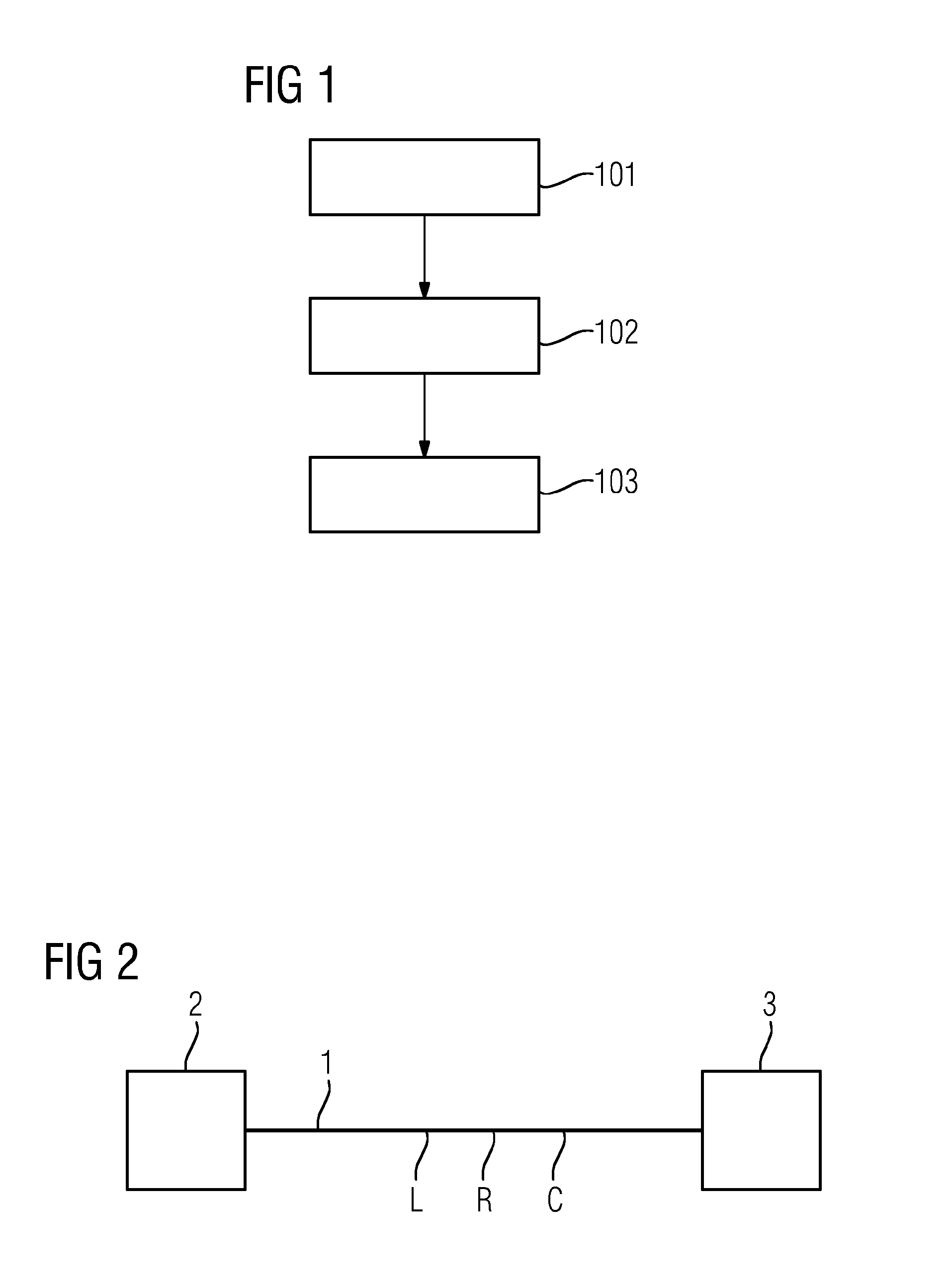
[0060]FIG. 1 illustrates a flow chart of a first example of a method for recognizing a manipulation on an electrical line 1. FIG. 2 shows a block circuit diagram of the electrical line 1 with a first coupled component 2 and a second coupled component 3. As used herein, the terms component and communication subscriber are used synonymously. The electrical line 1 is, for example, an electrical line. The electrical line 1 has a specific resistance R, a specific inductance L, and a specific capacitance C.

[0061]In act 101, a defined parameter that is dependent on the resistance R and the capacitance C and / or the inductance L of the electrical line 1 is determined. In act 102, the determined parameter is compared with a reference parameter to provide a comparison result. In act 103, a manipulation of the electrical line 1 is recognized on the ...


PUM


Abstract

A method for recognizing a manipulation of at least one electrical line includes determining a parameter that is dependent on a resistance and a capacity, a resistance and an inductivity, or a resistance, a capacity, and an inductivity of the electrical line; comparing the determined parameter to a reference parameter to provide a comparison result; and recognizing a manipulation of the electrical line based on the provided comparison result.

Description

RELATED APPLICATIONS[0001]This application is the National Stage of International Application No. PCT / EP2013 / 055257, filed Mar. 14, 2013, which claims the benefit of German Patent Application No. DE 102012206870.8, filed Apr. 25, 2012. The entire contents of both documents are hereby incorporated herein by reference.TECHNICAL FIELD[0002]The present teachings relate generally to a method and an apparatus for recognizing a manipulation on an electrical line. The electrical line may be, for example, a communication line, a communication bus, a data or address line, a supply line, a line that is selectively used for supply and communication, a line on a printed circuit board between electronic components (e.g., integrated circuits) or a line that is connected only on one side (e.g., floating gate).BACKGROUND[0003]There are various methods for recognizing manipulation attempts on electrical lines and on electronic circuits. The different methods may be divided into methods with and witho...

Claims


Application Information

Patent Timeline
IPC IPC(8): G01R27/26
CPCG01R27/2611G01R27/2605G06F21/85G06F21/86G08B29/08G08B29/24Y04S40/20
Inventor DICHTL, MARKUSMEYER, BERND
Owner SIEMENS AG
Learn More