Controllable lighting assembly

a technology of lighting assembly and control panel, which is applied in the field of lighting, can solve the problems of affecting the quality of radio communication, mainly dissipating heat generated by leds in a non-lighting direction, and expensive end components, etc., and achieves the effects of broad bandwidth, less sensitive, and broad bandwidth

Active Publication Date: 2015-04-23
SIGNIFY HLDG BV
View PDF6 Cites 18 Cited by
  • Summary
  • Abstract
  • Description
  • Claims
  • Application Information

AI Technical Summary

Benefits of technology

[0008]According to an example embodiment of the present invention, the heat sink and the lamp foot may be electrically insulated and arranged at a predefined distance from each other. Furthermore, the second antenna arrangement may form a dipole antenna having a first conductor element formed by the lamp foot and a second conductor element formed by the heat sink. Accordingly, the predefined distance between the heat sink and the lamp foot form a gap of the dipole antenna. An advantage is, at least, that the electrically insulated gap between the heat sink and the lamp foot may provide a beneficial environment for coupling a radio frequency signal between the second antenna arrangement and the first antenna arrangement when, for example, wirelessly controlling the lighting assembly.
[0009]Furthermore, the lighting assembly may be a retrofit lighting assembly connectable to a standard socket (by means of the lamp foot), and the heat sink may be a conic shaped heat sink. The lamp foot may hence be arranged in a plurality of shapes and sizes to fit with a socket having e.g. standard dimensions E14, E17, E26, E27, E39, etc. Also, the conic shape of the heat sink may enable for a broad bandwidth dipole antenna, which may be comparable to e.g. already known bow-tie antennas or log-periodic antennas having a relatively broad bandwidth. An advantage of having a broad bandwidth is, as also described above, that the antenna arrangement may be less sensitive to centre frequency shifting, which may occur when e.g. the lighting assembly is inserted into e.g. a luminaire which will load the first antenna arrangement.
[0010]Furthermore, the first antenna arrangement may be provided inside the lighting assembly being at least partially enclosed by the heat sink. The first antenna arrangement may act as an excitation antenna and may hence be the only one of the first and the second antenna arrangement which is electrically connected to the mains network. Accordingly, by providing the first antenna arrangement within the lighting assembly, the electrically connected first antenna arrangement will not be accessible from the exterior, which in turn further increases the safety for a user handling the lighting assembly.
[0011]According to an example embodiment, the first antenna arrangement may be provided on a printed circuit board connected to the at least one light source. An advantage is that an already present printed circuit board arranged within the lighting assembly may be provided with the first antenna arrangement, thereby not increasing the number of components and the complexity of the lighting assembly.
[0012]According to another example embodiment of the present invention, the first antenna arrangement may be formed by a ring-shaped metallic conductor element connected to the at least one light source. Hereby, a relatively simple metallic object may be connected to the light source for providing an antenna element. Another advantage is that a relatively compact element may be provided which may efficiently couple to the above described gap between the heat sink and the lamp foot.
[0013]Moreover, the antenna arrangements may be configured to operate at a radio frequency of at least 2 GHz. The dimensioning of the elements constituted by the second antenna arrangement, i.e. the heat sink and the lamp foot, is readily understood and can be implemented by the skilled addressee. For example, if implementing the present invention to a retrofit lighting assembly where the heat sink and the lamp foot has a height of e.g. approximately 3 cm, the use of a 2.4 GHz radio frequency level may be suitable according to standardized dipole antenna calculations. However, the present invention should not be construed as limited to the use of specific dimensions of the heat sink and the lamp foot which may be provided in many other configurations as well.

Problems solved by technology

A challenge with LEDs is that heat generated by the LEDs is mainly dissipated in a non-lighting direction, in comparison to e.g. an incandescent light bulb dissipating heat in the direction of the light.
However, the provision of a metallic heat sink in e.g. close vicinity of wireless communication antennas provides for a problematic environment since the bulky metal may interact, through loading and shielding, with the antenna to negatively impact the quality of radio communication.
However, such implementation introduces complicated signal connection paths, resulting in an expensive end component.

Method used


Image

  • Controllable lighting assembly
  • Controllable lighting assembly
  • Controllable lighting assembly

Examples


Embodiment Construction

[0020]The present invention will now be described more fully hereinafter with reference to the accompanying drawings, in which currently preferred embodiments of the invention are shown. This invention may, however, be embodied in many different forms and should not be construed as limited to the embodiments set forth herein; rather, these embodiments are provided for thoroughness and completeness, and fully convey the scope of the invention to the skilled addressee. Like reference characters refer to like elements throughout.

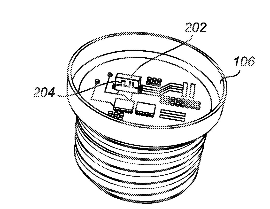
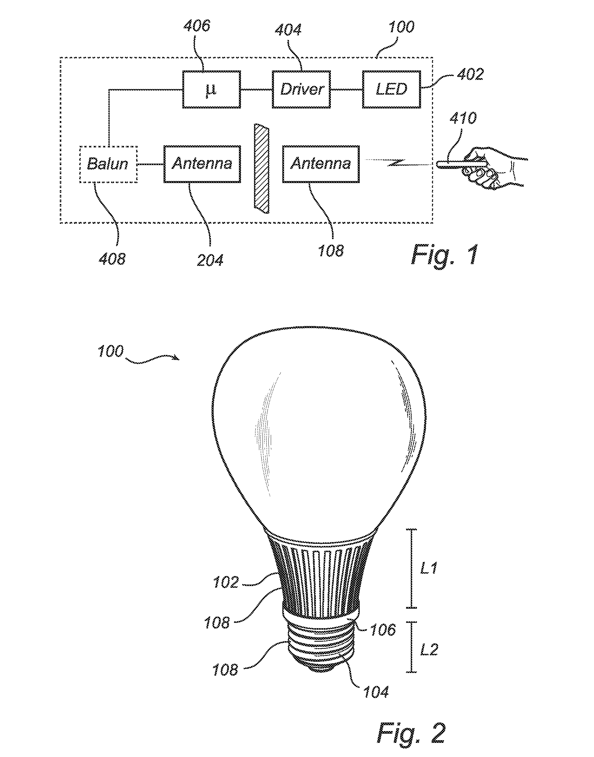
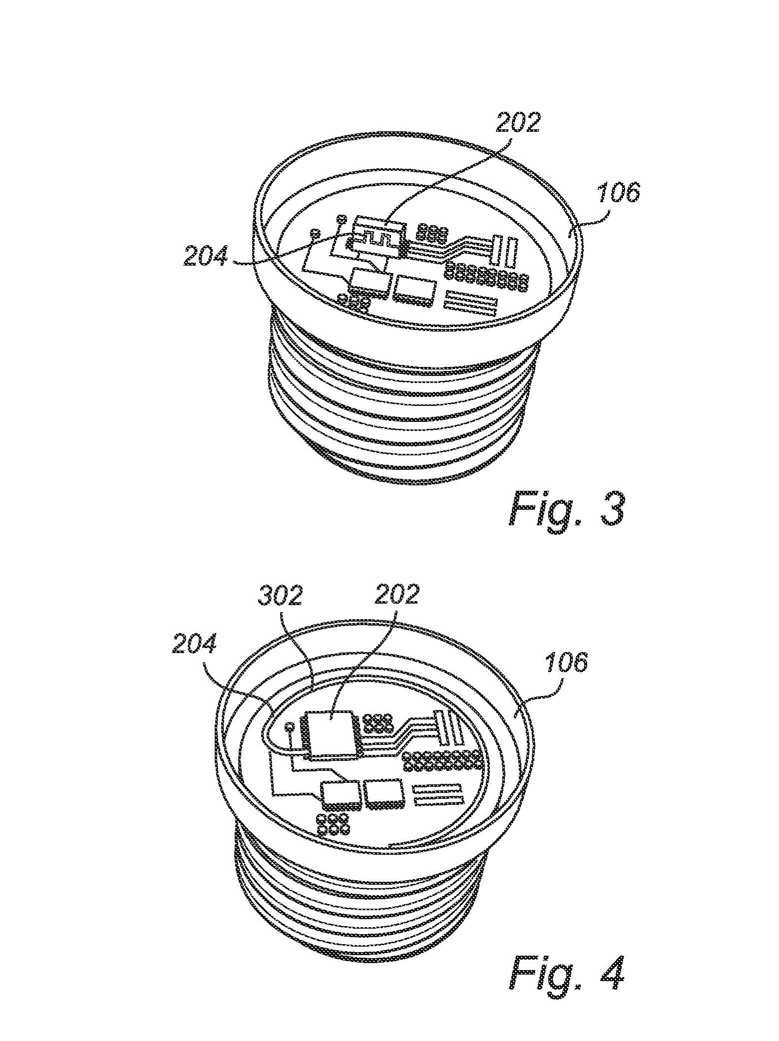
[0021]Referring now to the drawings and to FIG. 1 in particular, there is depicted an embodiment of a general concept for a lighting assembly 100 according to the present invention. In more detail, FIG. 1 illustrates a block diagram of a schematic circuit for wireless radio frequency control of the lighting assembly 100. As is depicted in FIG. 1, at least one light source 402 is connected to a driver 404 for electrically connecting the at least one light source...


PUM


Abstract

The present invention relates to a lighting assembly (100), comprising at least one light source (402), a heat sink (102) for dissipating heat generated during operation of the at least one light source (402), a lamp foot for connecting the at least one light source to a power supply, a control unit for controlling the at least one light source, and a first antenna arrangement (204) connected to the control unit and being electrically insulated from the heat sink (102) and the lamp foot (104), wherein the heat sink (102) and the lamp foot (104) form a second antenna arrangement (108), and the first antenna arrangement (204) is arranged in close vicinity of the second antenna arrangement (108) for allowing near-field coupling of a radio frequency signal provided to control the at least one light source (402).

Description

TECHNICAL FIELD[0001]The present invention relates to the field of lighting, and more specifically to a wirelessly controllable lighting assembly having an integrated antenna configuration at least partly formed by structural components of the lighting assembly.BACKGROUND OF THE INVENTION[0002]Light emitting diodes, LEDs, are employed in a wide range of lighting applications. As LEDs have the advantage of providing controllable light in a very efficient way, it is becoming increasingly attractive to use LEDs as an alternative light source instead of traditional incandescent and fluorescence light sources. Furthermore, LEDs are advantageous since they may allow for simple control in respect to e.g. dimming and color setting. This control may be realized through wireless radio frequency communication allowing for integration with e.g. wireless home automation systems, etc.[0003]A challenge with LEDs is that heat generated by the LEDs is mainly dissipated in a non-lighting direction, i...

Claims


Application Information

Patent Timeline
Patent Type & Authority Applications(United States)
IPC IPC(8): F21V29/70F21V23/00H05B37/02F21K99/00
CPCF21V29/70H05B37/0272F21V23/005F21K9/1355F21V23/0435H01Q1/22H01Q9/16F21V23/045F21K9/23F21V23/006F21K9/238H05B47/19H05B47/10F21V23/04
Inventor VAN DER MERWE, JACODENKER, ROGER HENRILOUH, YACOUBACLAESSENS, DENNIS JOHANNES ANTONIUSGEELS, MARIJNDE JONG, LAMBERTUS ADRIANUS MARINUS
Owner SIGNIFY HLDG BV
Why Eureka
Try Eureka