Resonant power conversion apparatus and controlling method thereof

a power conversion apparatus and control method technology, applied in the direction of electric variable regulation, process and machine control, instruments, etc., can solve the problems of increasing the switching loss of the resonant converter, the overcurrent protection is crucial, and the resonant power conversion apparatus is very likely to be damaged by high current, so as to limit the current flowing

Active Publication Date: 2015-04-23
FSP POWERLAND TECH +1
View PDF3 Cites 13 Cited by
  • Summary
  • Abstract
  • Description
  • Claims
  • Application Information

AI Technical Summary

Benefits of technology

[0009]The invention provides a resonant power conversion apparatus and a controlling method thereof which may limit a current flowing through a load by lowering a switching frequency of a resonant converter.

Problems solved by technology

In a resonant power conversion apparatus using the resonant converter, the over-current protection is a crucial issue.
If the resonant current is not limited or protected, the resonant power conversion apparatus is very likely to be damaged by high current.
However, while said over-current protection mechanism is activated, the switching frequency of the resonant converter is far higher than the normal frequency, thus leading to increase of switching loss of the resonant converter.
In addition, the stress tolerated by the magnetic components (e.g., capacitors or inductors) may be increased together with the increase of the switching frequency, and thus the magnetic components are more likely to be worn out.
In addition, the increasing switching frequency leads to the rising temperature of operating circuits, and hence the heat dissipation requirement for the resonant power conversion apparatus becomes rather difficult to comply with.

Method used


Image

  • Resonant power conversion apparatus and controlling method thereof
  • Resonant power conversion apparatus and controlling method thereof
  • Resonant power conversion apparatus and controlling method thereof

Examples


Embodiment Construction

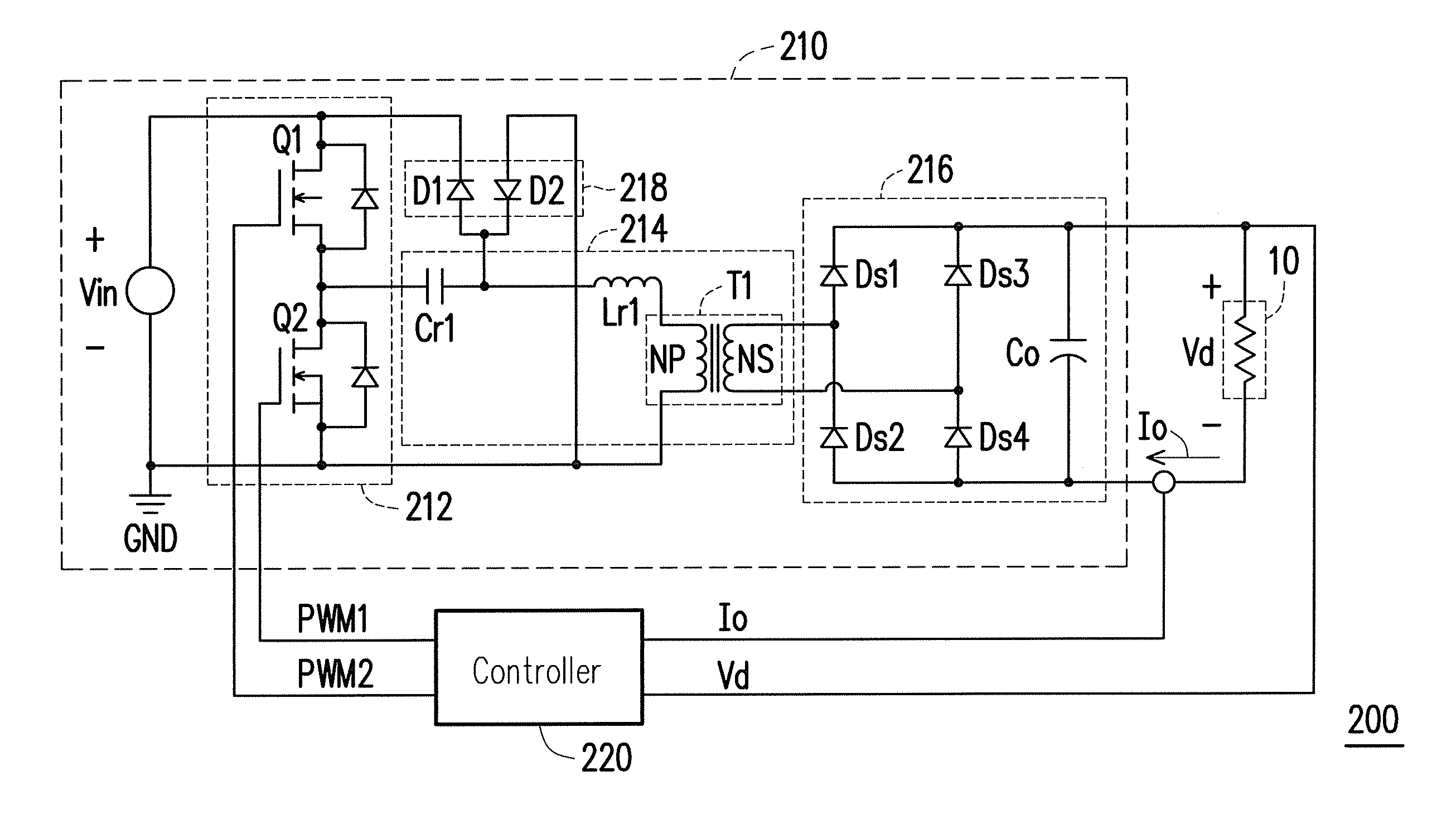
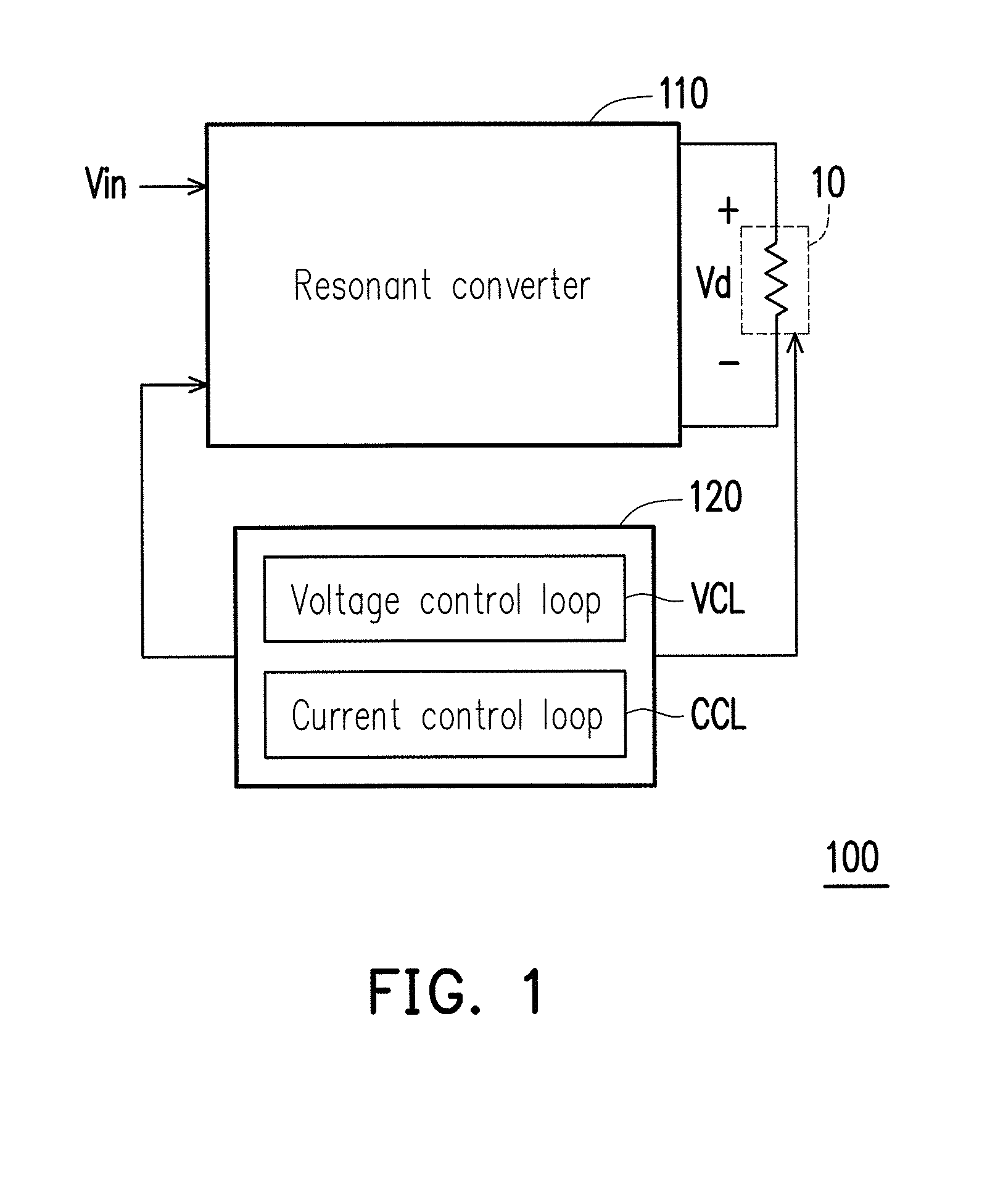
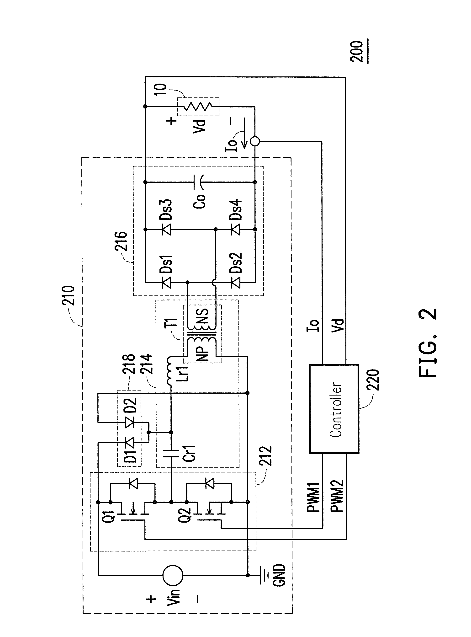
[0033]A resonant power conversion apparatus and a control method of the resonant power conversion apparatus are provided herein. The resonant power conversion apparatus may alternatively enable a voltage control loop (characterized by a reverse frequency regulating mechanism) or a current control loop (characterized by a forward frequency regulating mechanism) to control a switching frequency of a resonant converter. Since the current control loop described herein limits the current flowing through the load by a manner of reducing the switching frequency, the conventional issue of the switching loss caused by raising the switching frequency for limiting the current flowing through the load may be resolved. In order to make the invention more comprehensible, embodiments are described below as examples to prove that the invention can actually be realized. Moreover, elements / components / steps with same reference numerals represent same or similar parts in the drawings and embodiments.

[0...


PUM


Abstract

A resonant power conversion apparatus and a controlling method of the resonant power conversion apparatus are provided. The resonant power conversion apparatus includes a switch-based resonant converter and a controller. The switch-based resonant converter is configured to supply power to a load. The controller is coupled to the switch-based resonant converter and the load and configured to control switching of the switch-based resonant converter to regulate power conversion of the switch-based resonant converter. The controller has a voltage control loop and a current control loop. The controller detects a driving state of the load and enables one of the voltage control loop and the current control loop according to the detection result to adjust a switching frequency of the switch-based resonant converter.

Description

CROSS-REFERENCE TO RELATED APPLICATION[0001]This application claims the priority benefit of China application serial no. 201310487086.0, filed on Oct. 17, 2013. The entirety of the above-mentioned patent application is hereby incorporated by reference herein and made a part of this specification.BACKGROUND OF THE INVENTION[0002]1. Field of Invention[0003]The invention relates to a power conversion technique and more particularly to a resonant power conversion apparatus and a controlling method thereof.[0004]2. Description of Related Art[0005]The development trend of direct current (DC) converters, similar to that of most power supply products, is toward high efficiency, high power density, high reliability, and low costs. Since resonant converters (e.g., LLC resonant converters, etc.) are capable of performing zero-voltage switching (ZVS) in the primary winding and zero-current switching (ZCS) in the secondary winding on the full-load range, the resonant converters have gradually be...

Claims


Application Information

Patent Timeline
Patent Type & Authority Applications(United States)
IPC IPC(8): H02M3/335H02M1/00
CPCH02M3/33507H02H9/02H02M3/28H02M3/01H02M3/33571Y02B70/10Y02P80/10H02M1/0058
Inventor XU, MINGDUAN, FEI-YUE
Owner FSP POWERLAND TECH
Why Eureka
Try Eureka