
System and Method for Transducer Biasing and Shock Protection

Active Publication Date: 2015-04-23
INFINEON TECH AG
View PDF1 Cites 5 Cited by
  • Summary
  • Abstract
  • Description
  • Claims
  • Application Information

AI Technical Summary

Benefits of technology

The patent describes an interface circuit that includes an amplifier and two bypass circuits. The first bypass circuit is connected to a reference voltage and the amplifier, and it conducts a current when an input signal amplitude exceeds a certain threshold. The control circuit then activates the second bypass circuit for a specific period of time. This circuit design allows for efficient amplification and signal processing, with improved accuracy and reliability.

Problems solved by technology

In many applications, large amplitude physical signals caused by shock or similar events can overload the MEMS device and permanently or temporarily affect performance.
In a MEMS microphone, shock events may affect an amount of charge on the capacitive plates.

Method used


Image

  • System and Method for Transducer Biasing and Shock Protection
  • System and Method for Transducer Biasing and Shock Protection
  • System and Method for Transducer Biasing and Shock Protection

Examples


Embodiment Construction

[0016]The making and using of various embodiments are discussed in detail below. It should be appreciated, however, that the various embodiments described herein are applicable in a wide variety of specific contexts. The specific embodiments discussed are merely illustrative of specific ways to make and use various embodiments, and should not be construed in a limited scope.

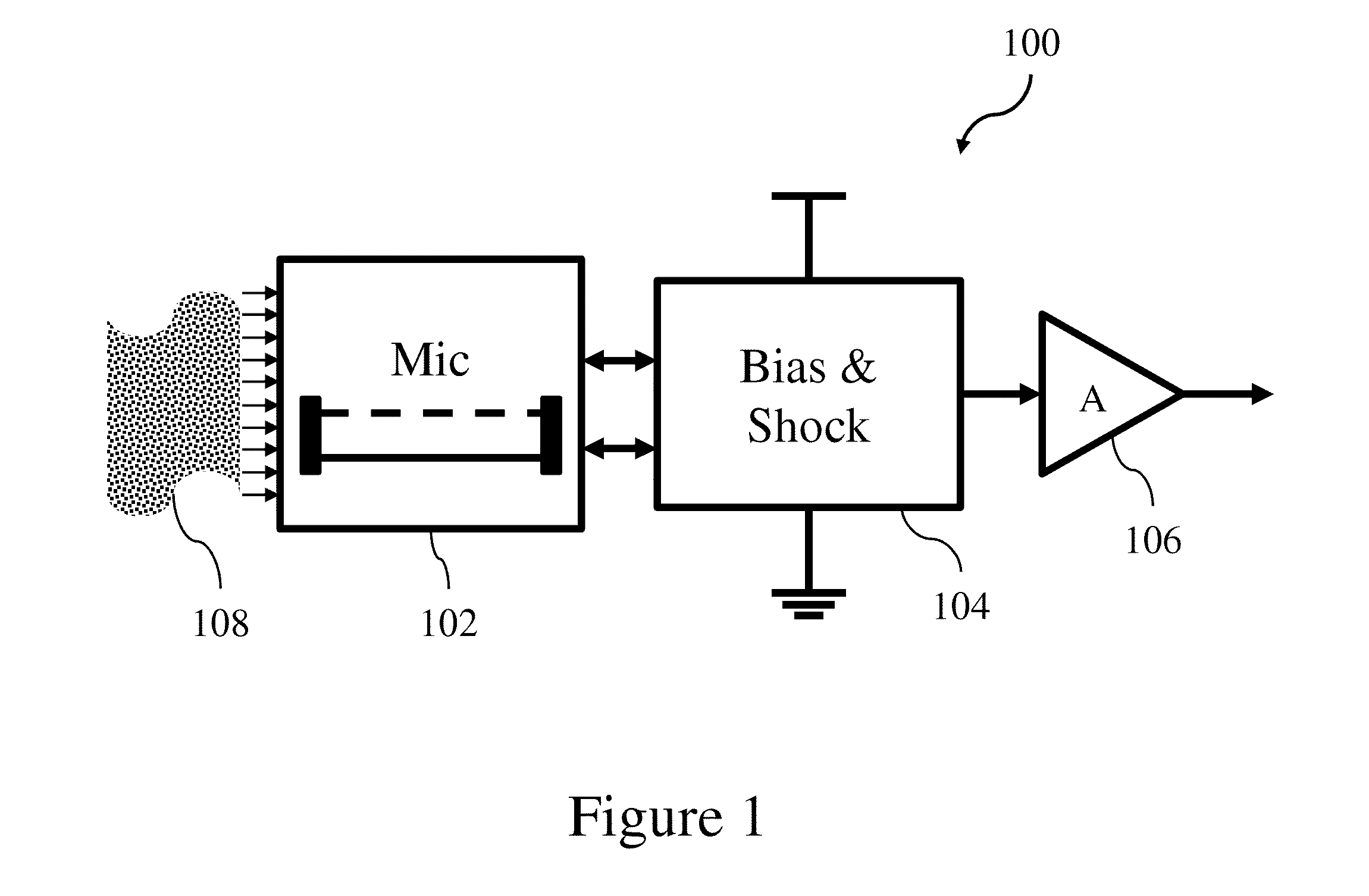
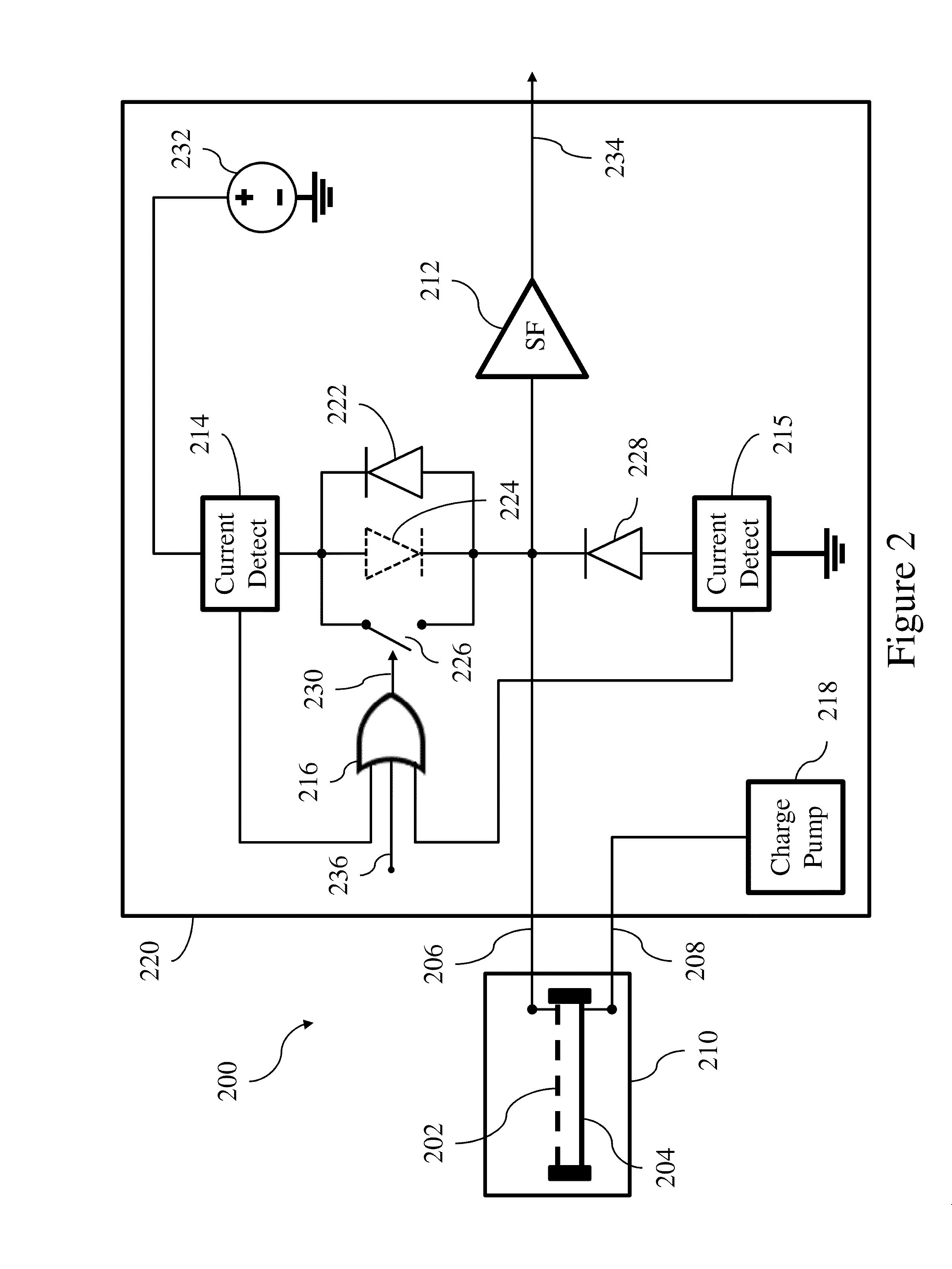
[0017]Description is made with respect to various embodiments in a specific context, namely microphone transducers, and more particularly, MEMS microphones. Some of the various embodiments described herein include MEMS transducer systems, MEMS microphone systems, interface circuits for transducer and MEMS transducer systems, biasing circuits for MEMS transducer systems, and shock protection and recovery for MEMS transducer systems. In other embodiments, aspects may also be applied to other applications involving any type of sensor or transducer converting a physical signal to another domain and interfacing with e...


PUM


Abstract

In accordance with an embodiment, an interface circuit includes an amplifier configured to be coupled to a transducer, a first bypass circuit coupled to a first voltage reference and the amplifier, a second bypass circuit coupled to the first voltage reference and the amplifier, and a control circuit coupled to the second bypass circuit. The first bypass circuit conducts a current when an input signal amplitude greater than a first threshold is applied to the transducer and the control circuit causes the second bypass circuit to conduct a current for a first time period after the first bypass circuit conducts a current.

Description

TECHNICAL FIELD[0001]The present invention relates generally to transducers, and, in particular embodiments, to a system and method for transducer biasing and shock protection.BACKGROUND[0002]Transducers convert signals from one domain to another and are often used in sensors. A common sensor with a transducer that is seen in everyday life is a microphone, a sensor for audio signals with a transducer that converts sound waves to electrical signals.[0003]Microelectromechanical system (MEMS) based sensors include a family of transducers produced using micromachining techniques. MEMS, such as a MEMS microphone, gather information from the environment through measuring physical phenomena, and electronics attached to the MEMS then process the signal information derived from the sensors. MEMS devices may be manufactured using micromachining fabrication techniques similar to those used for integrated circuits.[0004]Audio microphones are commonly used in a variety of consumer applications s...

Claims


Application Information

Patent Timeline
IPC IPC(8): H04R3/00H04R17/02H04R1/08
CPCH04R3/00H04R17/02H04R1/08H04R3/007H04R2201/003H04R2410/00
Inventor JENKNER, CHRISTIANGAGGL, RICHARDMUEHLBACHER, BENNO
Owner INFINEON TECH AG
Features
  • Generate Ideas
  • Intellectual Property
  • Life Sciences
  • Materials
  • Tech Scout
  • Unparalleled Data Quality
  • Higher Quality Content
  • 60% Fewer Hallucinations
Learn More