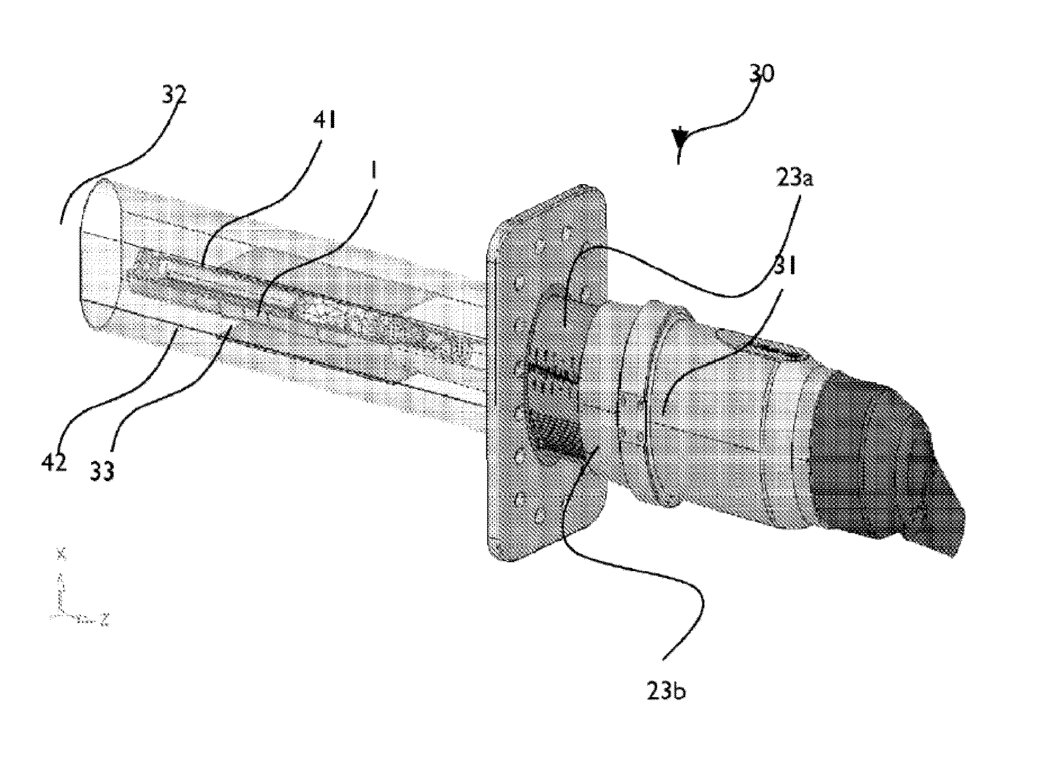
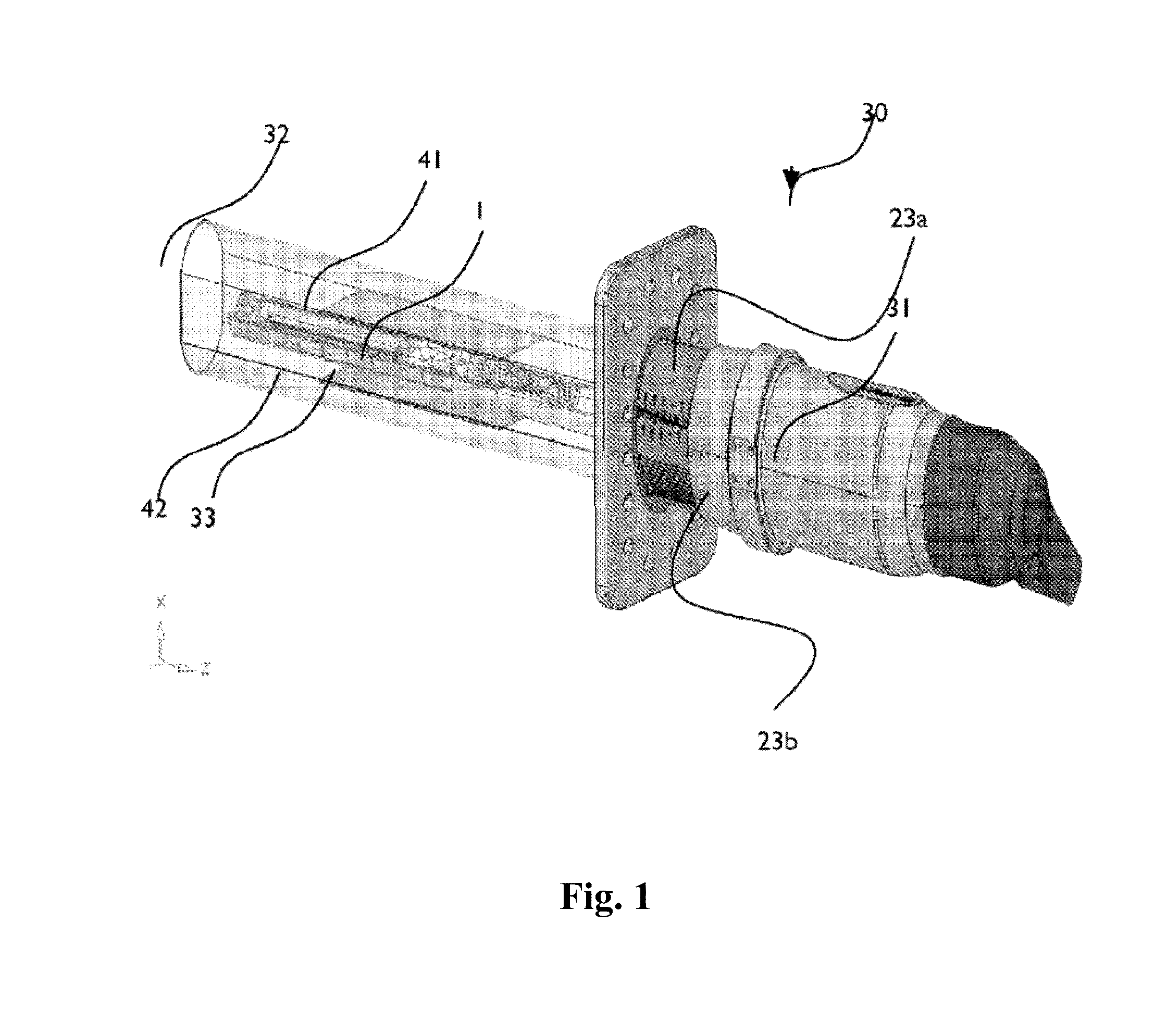
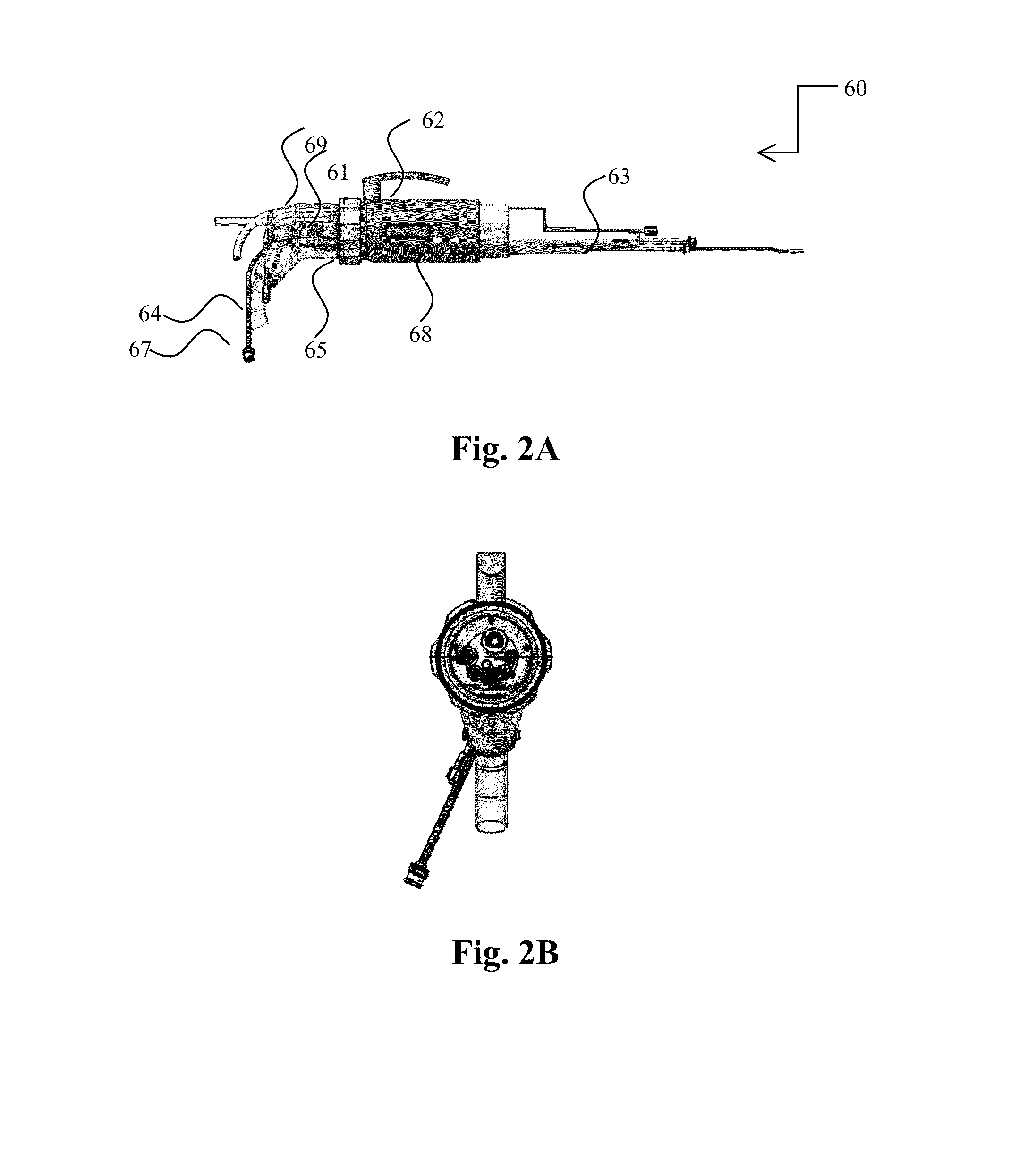
MRI with magnet assembly adapted for convenient scanning of laboratory animals with automated RF tuning unit

a technology of magnet assembly and laboratory animal, applied in the field of magnet assembly, can solve the problems of limited free space in the effective space of the mri device, low scanning resolution, and high cost of the device, and achieve the effect of improving the scan resolution

Active Publication Date: 2015-04-23
ASPECT IMAGING
View PDF0 Cites 23 Cited by
  • Summary
  • Abstract
  • Description
  • Claims
  • Application Information

AI Technical Summary

Benefits of technology

[0009]It is thus one object of the invention to disclose an MRD comprising a plurality of main magnets positioned in a substantial horizontal plane and a plurality of surface plates or coils magnets positioned in a substantial vertical plane. Another object is to disclose a method of using the same such that improved MRI scans are obtained.

Problems solved by technology

The effective free space within an MRI device, especially lab-scale and experimental MRI devices is very much limited.
Hence, either the MRI device is designed to be big enough to accommodate the object, and thus the device is much more expensive, or the scanning resolution is relatively low.
This technology is not implementable in small laboratory-scale MRI devices and scanned object must be tilted and otherwise maneuvered such that optimal imaging is obtained.
Currently, this tuning mechanism involves manually mechanically adjusting the location of the RF coils with respect to the magnetic field, thereby causing a change in the RE field.
Such manual systems involve trial and error and are prone to elaborate and lengthy calibration.
None of the above provides a simple solution for precise positioning of the animal within an MRI device.

Method used


Image

  • MRI with magnet assembly adapted for convenient scanning of laboratory animals with automated RF tuning unit
  • MRI with magnet assembly adapted for convenient scanning of laboratory animals with automated RF tuning unit
  • MRI with magnet assembly adapted for convenient scanning of laboratory animals with automated RF tuning unit

Examples


Embodiment Construction

[0017]The following description is provided in order to enable any person skilled in the art to make use of the invention and sets forth the best modes contemplated by the inventor of carrying out this invention. Various modifications, however, will remain apparent to those skilled in the art, since the generic principles of the present invention have been defined specifically to provide an MRI device with a plurality of enter ports and to methods using the same.

[0018]The term ‘Magnetic Resonance Device’ (MRD) specifically applies hereinafter to any Magnetic Resonance Imaging (MRI) device, any Nuclear Magnetic Resonance (NMR) spectroscope, any Electron Spin Resonance (ESR) spectroscope, any Nuclear Quadruple Resonance (NQR) spectroscope or any combination thereof. The MRD hereby disclosed is optionally a portable MRI device, such as the ASPECT Magnet Technologies Ltd commercially available devices, or a commercially available non-portable device. The MRD hereby disclosed is optional...


PUM


Abstract

An animal handling system (AMS), for positioning an immobilized animal in a predefined configuration therein, comprising an automated tuning unit, including: a proximal portion, held outside a medical device including: at least one inner shaft, and at least one outer shaft, the at least one inner is telescopically maneuverable within the at least one outer shaft providing a variable telescopic mechanism; and a distal portion including: a configurable encapsuable life support system (ELSS), the ELSS is rotatable about a longitudinal axis of the at least outer shaft and the at least inner shaft and translationally moveable parallel to the longitudinal axis by means of the maneuverable telescopic mechanism.

Description

FIELD OF THE INVENTION[0001]The present invention generally pertains to MRI with magnet assembly adapted for convenient scanning of laboratory animals, containing an automated RF tuning unit.BACKGROUND OF THE INVENTION[0002]Commercially available MRI devices typically consist of main magnets which are positioned in parallel and horizontally. Surface coils (also known as surface plates) are essentially loops of conducting material, such as copper tubing. Surface coils are commonly positioned in a plane being substantially perpendicular to the plane of the main magnets. The surface coils are placed directly on or over the region of interest for increased magnetic sensitivity, more information is available at http: / / www.mr-tip.com.[0003]The positioning of the coil is an important determinant of performance. As only the region close to the surface coil will contribute to the signal, there is an improvement in the signal to noise ratio for these regions, compared to the use of receiver c...

Claims


Application Information

Patent Timeline
Patent Type & Authority Applications(United States)
IPC IPC(8): A61B5/055A01K1/03A01K1/06G01R33/30G01R35/00
CPCA61B5/0555G01R33/30A01K1/03A01K1/0613G01R35/00G01R33/341G01R33/383G01R33/3628A61B5/055A61B2503/40A61B2503/42A61D3/00G01R33/583
Inventor RAPOPORT, URIRABINOVITZ, ITZCHAK
Owner ASPECT IMAGING
Why Eureka
Try Eureka