Data correction method in fine particle measuring device and fine particle measuring device

Active Publication Date: 2015-04-23
SONY CORP
View PDF8 Cites 6 Cited by
  • Summary
  • Abstract
  • Description
  • Claims
  • Application Information

AI Technical Summary

Benefits of technology

The patent provides a technique that can accurately measure the brightness and color of fluorescence and scattered light, while accounting for errors caused by changes in the position of fine particles in a channel.

Problems solved by technology

In the fine particle measurement device, the laminar flow is formed so that the fine particles flow substantially in the center of the channel, but the flow position of each fine particle in the channel varies, and therefore, measurement error caused by this variation is problematic.
As a result, measurement error caused by the deviation of the optical position occurs in the intensity and the spectrum of the fluorescence and the scattered light detected in each fine particle.

Method used


Image

  • Data correction method in fine particle measuring device and fine particle measuring device
  • Data correction method in fine particle measuring device and fine particle measuring device
  • Data correction method in fine particle measuring device and fine particle measuring device

Examples


Embodiment Construction

[0040]A preferred embodiment for carrying out the present technique will be hereinafter explained with reference to drawings. The embodiment explained below shows an example of a typical embodiment of the present technique, and it is to be understood that the scope of the present technique should not be interpreted as being narrower because of the embodiment. The explanation will be made in the following order.

1. Configuration of fine particle measurement device

(1) Measurement unit

[0041](1-1) Light illumination unit

[0042](1-2) Light detection unit

[0043](1-3) Position detection unit

(2) Arithmetic computation unit

2. Data correction processing in fine particle measurement device

(1) Correction target

(2) Correction processing

3. Modification

[0044](1) Light detection unit

(2) Position detection unit

4. Data correction method and data correction program

1. Configuration of Fine Particle Measurement Device

(1) Measurement Unit

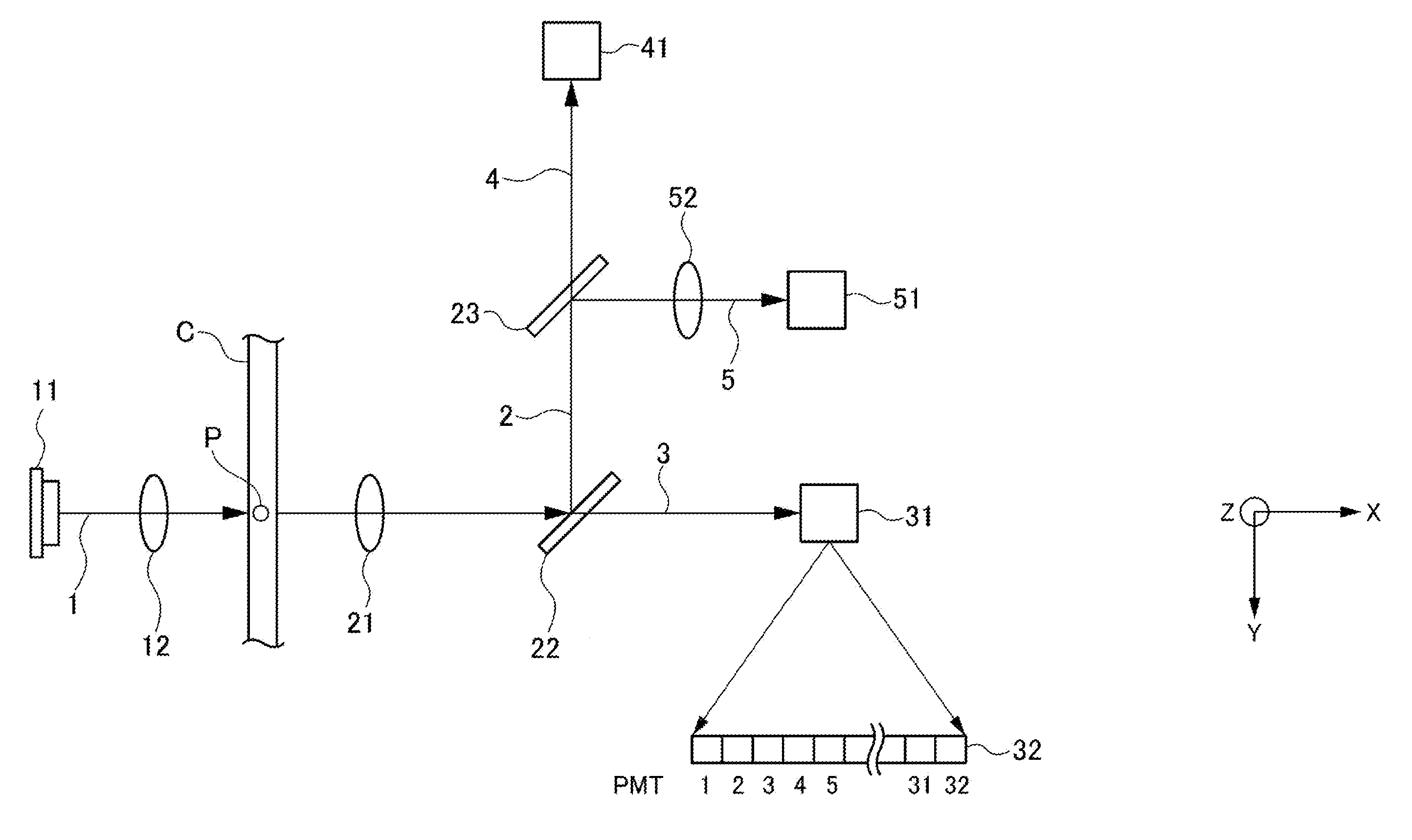
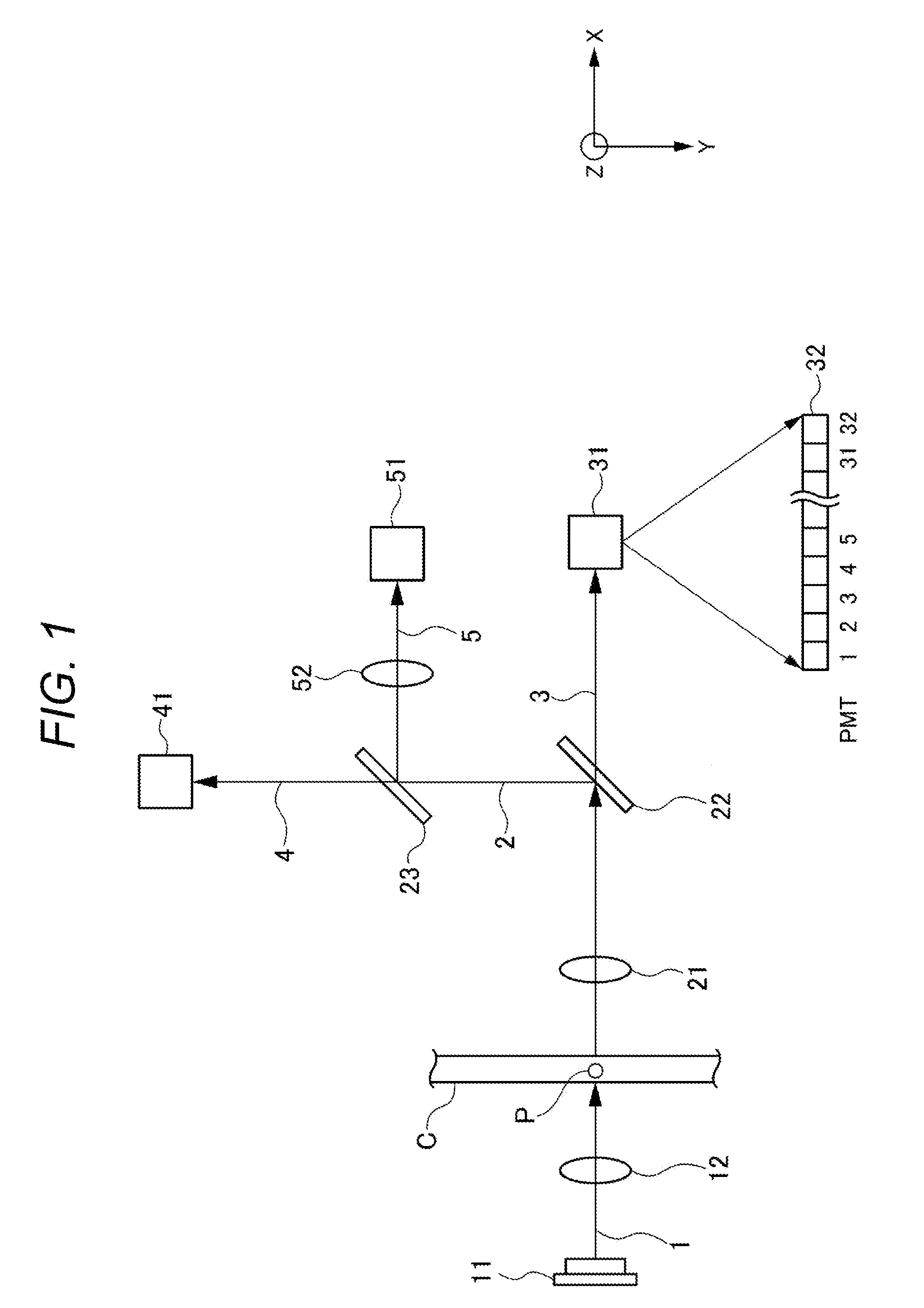
[0045]FIG. 1 is a figure for explaining a configuration of a measureme...


PUM


Abstract

To provide a technique capable of highly accurately measure the intensity and the spectrum of fluorescence and scattered light by effectively correcting measurement error that occurs due to variation of flow positions of fine particles in a channel. A data correction method for a fine particle measurement device is provided, which includes an intensity detection procedure capable of detecting light generated from a fine particle by emitting light onto the fine particle flowing through a channel, and obtaining intensity information about the light, a position detection procedure capable of obtaining position information about the fine particle, and a correction procedure for correcting the intensity information on the basis of the position information.

Description

TECHNICAL FIELD[0001]The present technique relates to a data correction method for a fine particle measurement device and a fine particle measurement device. More specifically, the present technique relates to, e.g., a data correction method for a fine particle measurement device for correcting measurement error caused by variation of flow positions of fine particles in a channel formed in a flow cell, a microchip, and the like.BACKGROUND ART[0002]A fine particle measurement device is known, which forms a laminar flow (which is also referred to as a sheath flow) including fine particles in a channel formed in a flow cell, a microchip, and the like, emits light onto the fine particles in the laminar flow, and detects fluorescence and scattered light generated from the fine particles. For example, a flow cytometer can measure and analyze the optical property of the fine particles such as cells and beads on the basis of the intensity or the spectrum of the fluorescence or the scattered...

Claims


Application Information

Patent Timeline
IPC IPC(8): G01N21/64G01B21/00
CPCG01B21/00G01N21/64G01N15/1429G01N21/05G01N21/21G01N21/53G01N21/645G01N2015/1415G01N2015/1006G01N15/1459
Inventor NITTA, NAOIMANISHI, SHINGOTAKEUCHI, TAICHI
Owner SONY CORP
Why Eureka
Try Eureka