
Energy storage

a technology of energy storage and energy storage, applied in the field of energy storage, can solve the problems the effect of affecting the efficiency of energy storage, and the effect of reducing the amount of electricity produced by solar or wind power sources,

Active Publication Date: 2015-04-23
SONY EUROPE BV +1
View PDF15 Cites 10 Cited by
  • Summary
  • Abstract
  • Description
  • Claims
  • Application Information

AI Technical Summary

Benefits of technology

This patent describes a method for controlling the storage of electrical energy in a battery system by charging and discharging the battery based on future pricing data. The method involves detecting alternating charging and discharging opportunities, validating them by calculating the difference in price between the proposed charging or discharging occasion and the next later price in the pricing data, and then charging or discharging the battery accordingly. This technique helps to optimize battery storage based on price signals, and can also be used for other types of storage systems like rotational energy storage.

Problems solved by technology

A further complication in grid balancing arrangements applies to renewable energy sources.
While these renewable sources have many advantages in terms of their possibly lower use of non-renewable carbon resources, they suffer from a disadvantage in that the amount of electricity delivered at any instant in time can depend upon aspects of the natural environment which are outside the control of the electricity supply company.
For example, the sun may go behind a cloud or the wind may drop, all leading to a relatively sudden decrease in the amount of electricity produced from a solar or wind power source.
However creating an algorithm that will schedule the correct charging and discharging time from a predicted (or upfront auctioned) price table is not a straightforward task.

Method used


Image

  • Energy storage
  • Energy storage
  • Energy storage

Examples


Embodiment Construction

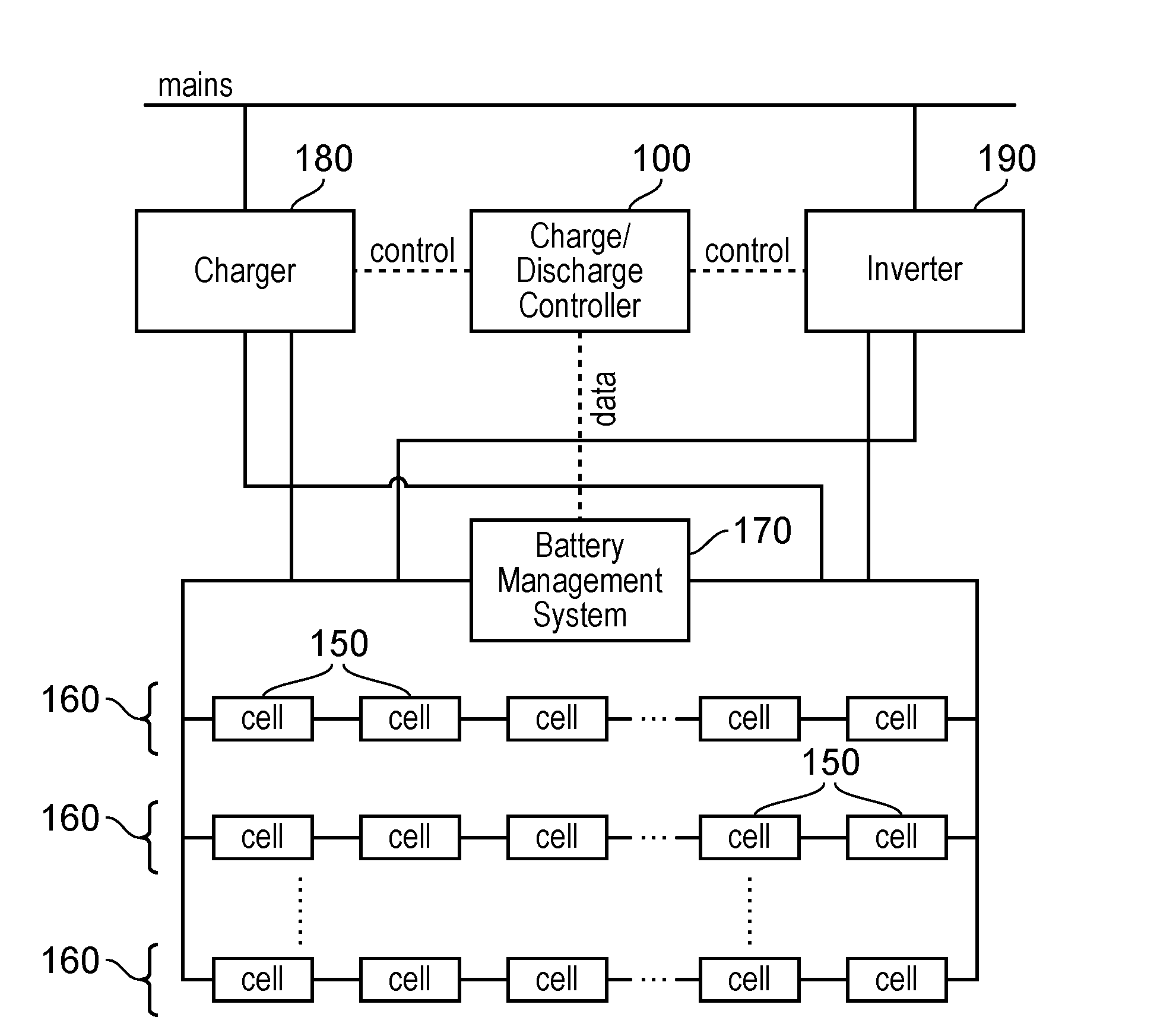
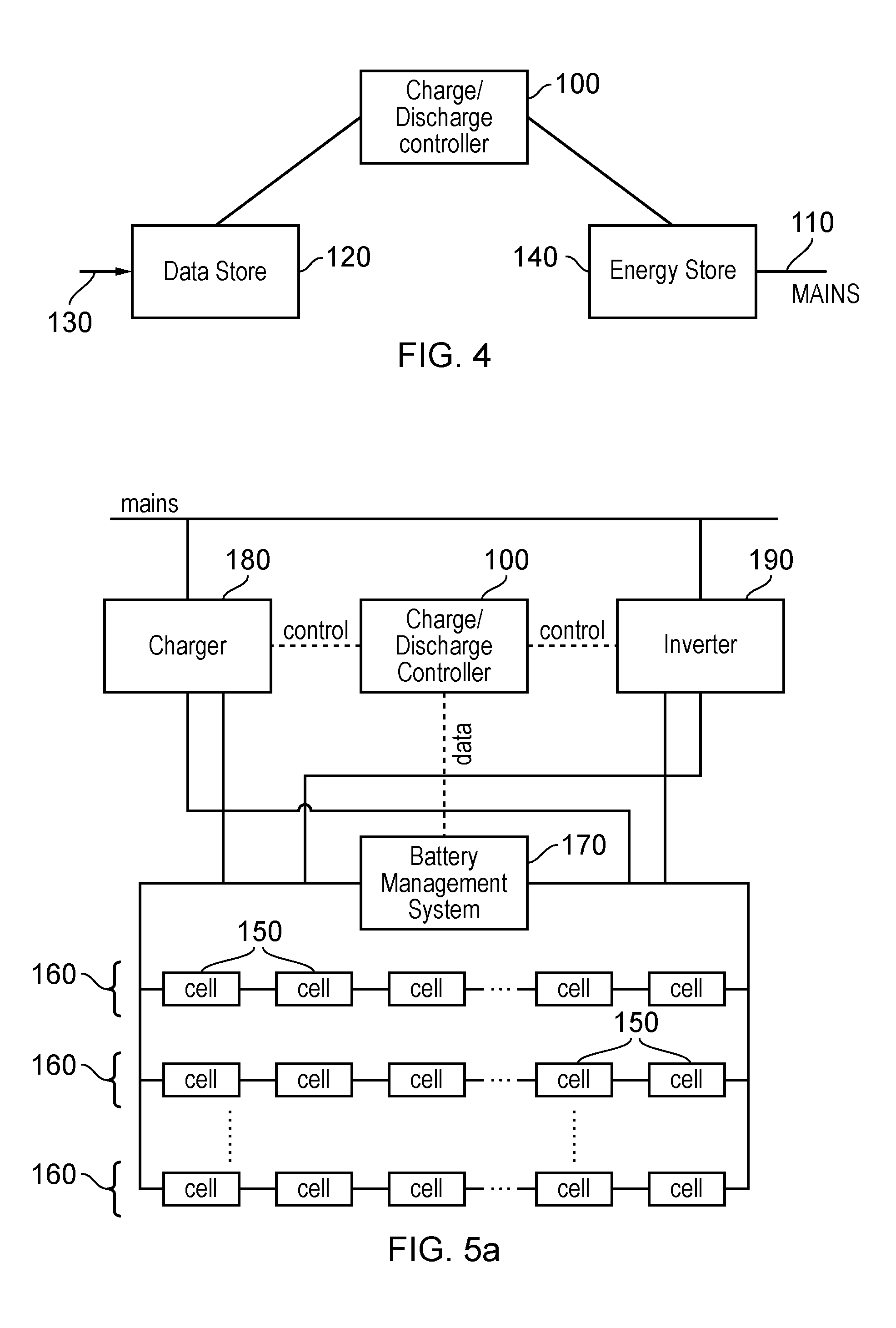
[0032]By way of introduction, a battery-based system to store and release grid power will first be described. Such an arrangement typically comprises:[0033]a) a battery charger, which converts mains voltage (such as 230 volts (V) alternating current (AC)) into a lower (for example, 48 V) direct current (DC) voltage[0034]b) a battery[0035]c) an inverter such as a so-called grid-tied inverter, which converts the DC voltage from the battery back into mains voltage (for example, 230 V AC voltage), or more generally, into a voltage higher than the battery voltage.

[0036]All three of these features can incur energy losses and therefore can be considered to exhibit a particular efficiency. The overall efficiency of the system is referred to as a “round-trip” efficiency to indicate that it represents a single efficiency figure linking the amount of energy input into the charge / discharge system to the amount of energy recovered from the system. The round-trip efficiency affects whether it is ...


PUM


Abstract

A method of controlling storage of electrical energy by charging and discharging an energy storage device in response to pricing data indicative of future prices of electrical energy over time and energy losses caused by charging and discharging the energy storage device comprises detecting alternating candidate charging and discharging occasions with respect to the pricing data by selecting a next occurrence of a locally minimum price in the pricing data as a candidate charging occasion or a next occurrence of a locally maximum price in the pricing data as a candidate discharging occasion; validating a candidate charging or discharging occasion if the price difference between that candidate charging or discharging occasion and another later price in the pricing data is at least sufficient to compensate for the energy losses caused by charging and discharging the energy storage device; and charging and discharging the energy storage device at the validated charging and discharging occasions, respectively.

Description

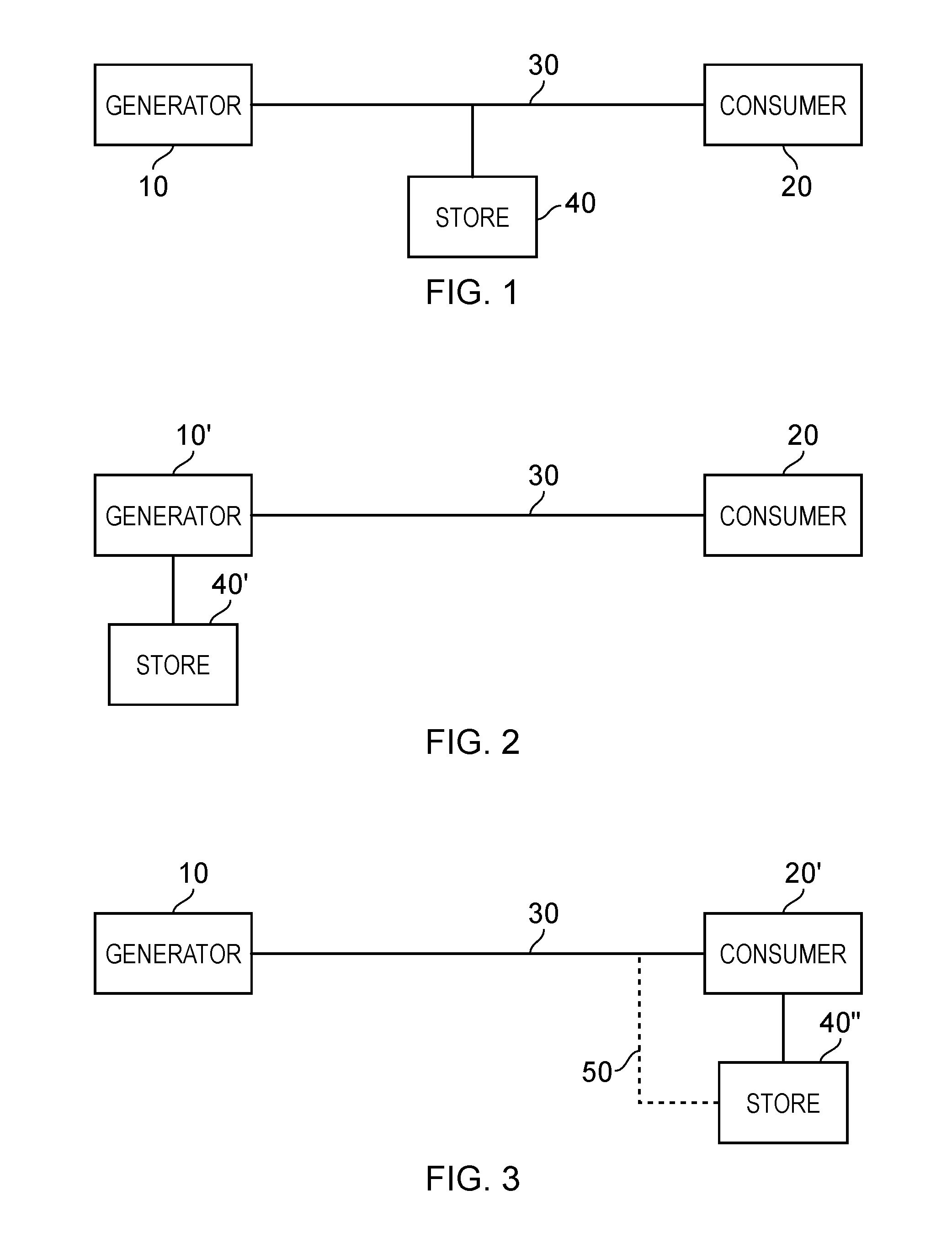
CROSS REFERENCE TO RELATED APPLICATION[0001]The present application claims the benefit of the earlier filing date of EP12162695.6 filed in the European Patent Office on 30 Mar. 2012, the entire content of which application is incorporated herein by reference.BACKGROUND[0002]1. Field[0003]This disclosure relates to energy storage.[0004]2. Description of the Prior Art[0005]The “background” description provided herein is for the purpose of generally presenting the context of the disclosure. Work of the presently named inventors, to the extent it is described in this background section, as well as aspects of the description which may not otherwise qualify as prior art at the time of filing, are neither expressly or impliedly admitted as prior art against the present disclosure.[0006]With decreasing battery prices, increasing battery capacity and the rise of renewable energy sources which introduce unpredictability to the energy production, battery storage for the electricity grid become...

Claims


Application Information

Patent Timeline
IPC IPC(8): G06Q10/06G06Q50/06H02J7/00
CPCG06Q10/06315G06Q50/06H02J7/007H02J3/14H02J3/32H02J2310/64Y02B70/3225Y04S20/222Y04S50/10
Inventor SPOOREN, JANRUTHERFORD, CHRISTOPHER
Owner SONY EUROPE BV
Learn More