Deposition apparatus

a technology of deposition apparatus and spherical plate, which is applied in the direction of chemical vapor deposition coating, coating, coating process, etc., can solve the problems of sub-layer material deterioration, sub-layer material oxidization, and damage to the substrate due to accelerated electrons, so as to prevent the effect of efficiency deterioration of the remote plasma process

Inactive Publication Date: 2015-04-30
ASM IP HLDG BV
View PDF3 Cites 226 Cited by
  • Summary
  • Abstract
  • Description
  • Claims
  • Application Information

AI Technical Summary

Benefits of technology

[0017]The present invention has been made in an effort to provide a deposition apparatus for preventing efficiency deterioration of a remote plasma process.
[0025]According to the deposition apparatus in accordance with the exemplary embodiment of the present invention, the efficiency deterioration of the remote plasma process can be prevented.

Problems solved by technology

When using the in-situ plasma method, there are problems of deteriorated characteristics of sub layer materials, such as substrate damage due to accelerated electrons, oxidization of the sub layer materials due to activated oxygen radicals, etc. because the plasma is generated on the substrate.
However, when using the remote plasma method, the active species may become extinct while being supplied to the reactor.
Particularly, when supply passages of the active species are complicated, such extinction of the active species may result from collision of the active species against inner walls of an active species supply conduit, chamber walls, or surfaces of a gas spraying means such as a showerhead.
Accordingly, as the passages inside the reactor are complicated, the active species generated by the remote plasma may become extinct to deteriorate efficiency of the remote plasma process.

Method used


Image

  • Deposition apparatus
  • Deposition apparatus
  • Deposition apparatus

Examples


Embodiment Construction

[0028]The present invention will be described more fully hereinafter with reference to the accompanying drawings, in which exemplary embodiments of the invention are shown.

[0029]As those skilled in the art would realize, the described embodiments may be modified in various different ways, all without departing from the spirit or scope of the present invention.

[0030]In the drawings, the thickness of layers, films, panels, regions, etc. are exaggerated for clarity.

[0031]Like reference numerals designate like elements throughout the specification.

[0032]It will be understood that when an element such as a layer, film, region, or substrate is referred to as being “on” another element, it can be directly on the other element or intervening elements may also be present.

[0033]In contrast, when an element is referred to as being “directly on” another element, there are no intervening elements present.

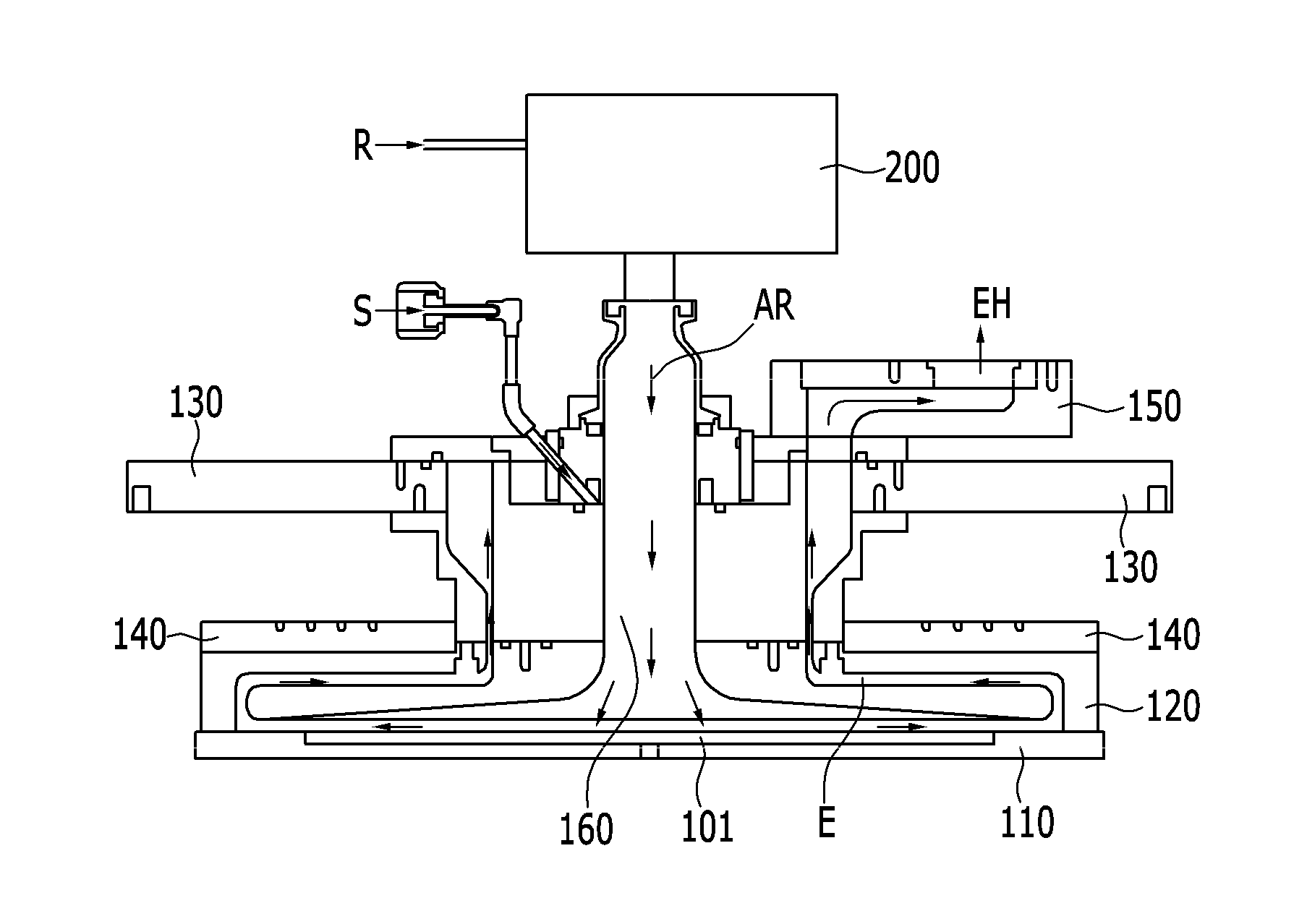
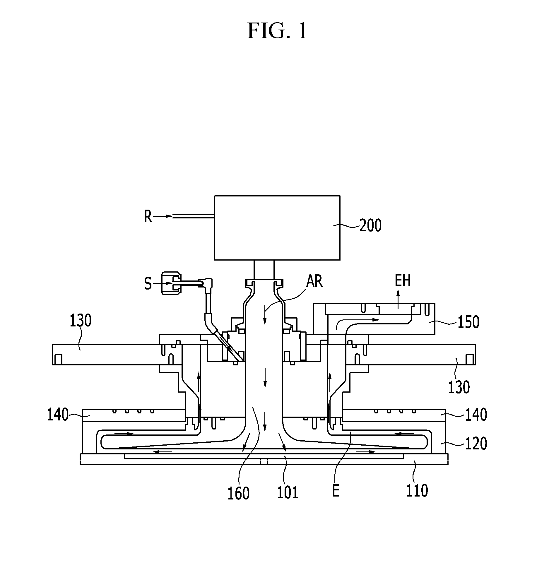
[0034]A deposition apparatus according to an exemplary embodiment of the present invention w...


PUM

PropertyMeasurementUnit
temperatureaaaaaaaaaa
radiusaaaaaaaaaa
temperatureaaaaaaaaaa

Abstract

An exemplary embodiment of the present invention provides a deposition apparatus including: a substrate support for supporting a substrate; a reaction chamber wall defining a reaction chamber and contacting the substrate support; a plurality of gas inlets connected to the reaction chamber wall; a remote plasma unit connected to at least one of the plurality of gas inlets; and a gas-supplying path connected to the plurality of gas inlets and defining a reaction region along with the substrate support. A plurality of gases passing through the plurality of gas inlets move along the gas-supplying path to be directly supplied onto the substrate without contacting other parts of the reactor.

Description

CROSS-REFERENCE TO RELATED APPLICATION[0001]This application claims priority to and the benefit of Korean Patent Application No. 10-2013-0129356 filed in the Korean Intellectual Property Office on Oct. 29, 2013, the entire contents of which are incorporated herein by reference.BACKGROUND OF THE INVENTION[0002](a) Field of the Invention[0003]The present invention relates to a deposition apparatus.[0004](b) Description of the Related Art[0005]In semiconductor deposition processes, a high temperature process at 500° C. or above has been frequently used to deposit chemical materials supplied to a reaction space in which a substrate is placed.[0006]However, as a size a semiconductor device gradually become smaller, there is a growing demand for a low temperature process to prevent deterioration of characteristics due to thermal shock.[0007]In such a low temperature process, a plasma process, in which plasma is used to activate a process gas, is introduced.[0008]When the plasma is used to...

Claims


Application Information

Patent Timeline
Patent Type & Authority Applications(United States)
IPC IPC(8): C23C16/50C23C16/455C23C16/44C23C16/46
CPCC23C16/50C23C16/4412C23C16/45561C23C16/46C23C16/452C23C16/45508H01L21/205
Inventor KIM, YOUNG HOONKIM, DAE YOUNJUNG, DONG RAKCHOI, YOUNG SEOKLEE, SANG WOOK
Owner ASM IP HLDG BV
Why Eureka
Try Eureka