Sheet conveying apparatus and image forming apparatus

a technology of conveying apparatus and sheet, which is applied in the direction of transportation and packaging, electrographic process, instruments, etc., can solve the problems of difficult to sufficiently correct shearing of the fibrous tissue, etc., and achieves the effect of reducing the difference, and improving the rippling of the sh

Inactive Publication Date: 2015-04-30
CANON KK
View PDF12 Cites 11 Cited by
  • Summary
  • Abstract
  • Description
  • Claims
  • Application Information

AI Technical Summary

Benefits of technology

[0020]According to the invention, since the tension force in the conveying direction is applied on the sheet, even when a difference in extension occurs between the center portion and the end portion of the sheet, it is possible to reduce the difference and to improve rippling of the sheet.
[0021]Furthermore, even in a case where the conditions such as a basis weight, a type, an image density, an environmental humidity are different, it is possible to apply the tension force on the sheet according to the conditions, and thus the rippling of the sheet can be more effectively improved.

Problems solved by technology

However, when the heat and the pressure are applied in the fixing process, the fibrous tissues are sheared.
However, a technology disclosed in U.S. Pat. No. 7,840,173 can correct the curls to make the sheet bent among the deformations of the sheet described above, but it is difficult to sufficiently correct the rippling of the sheet caused by a difference in extension occurring between the center portion and the end portion of the sheet.

Method used


Image

  • Sheet conveying apparatus and image forming apparatus
  • Sheet conveying apparatus and image forming apparatus
  • Sheet conveying apparatus and image forming apparatus

Examples


first embodiment

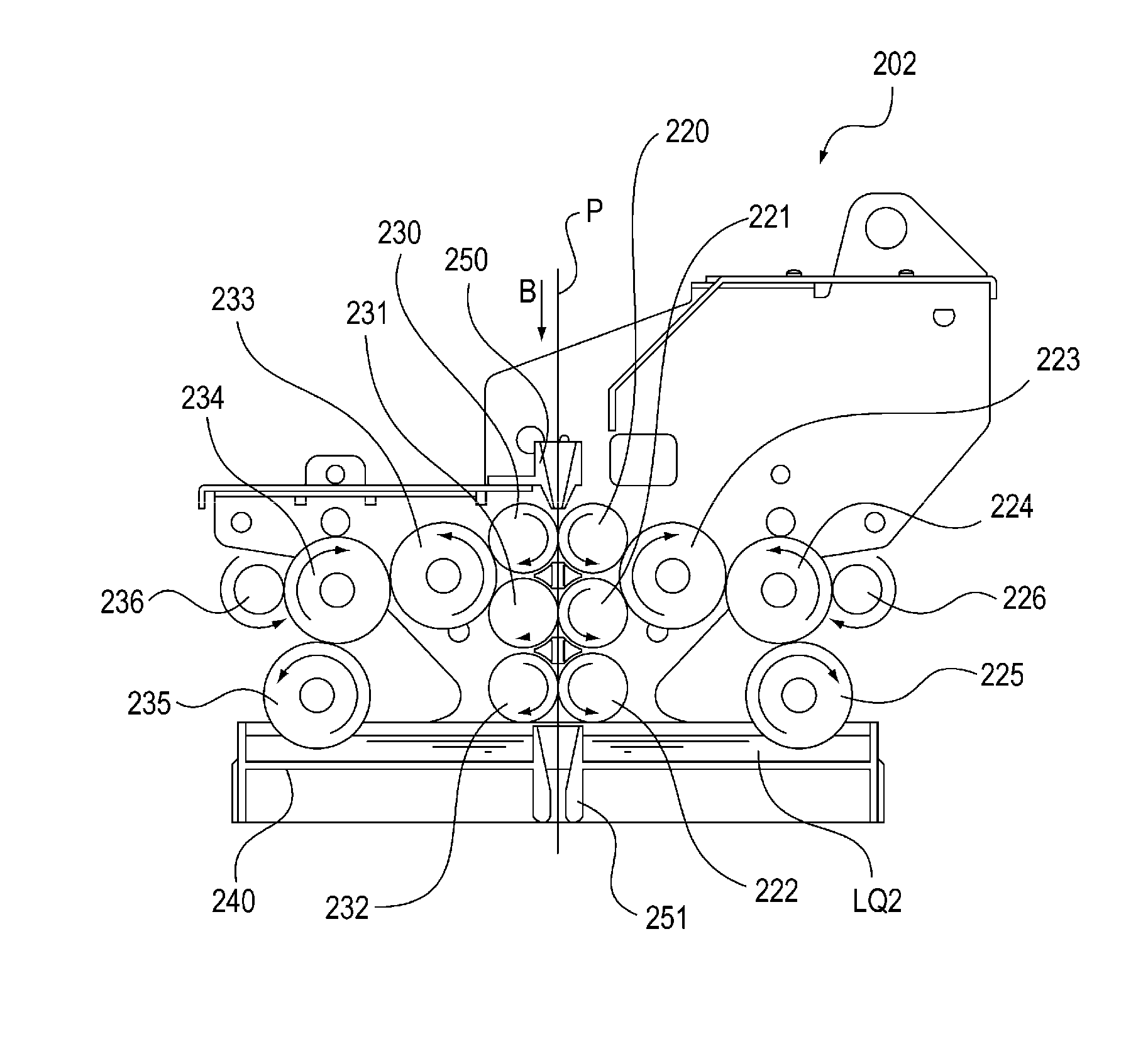
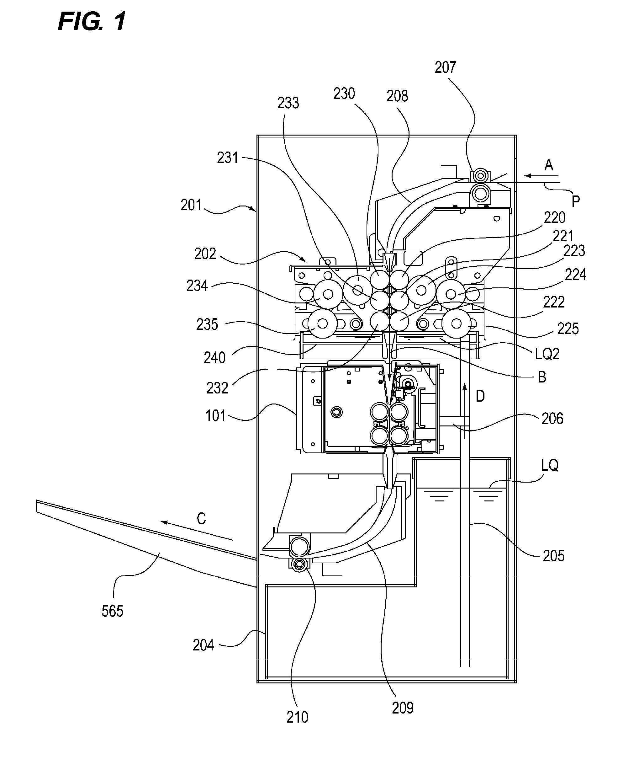
[0051]An image forming apparatus according to the embodiment will be described using FIGS. 1 to 14C.

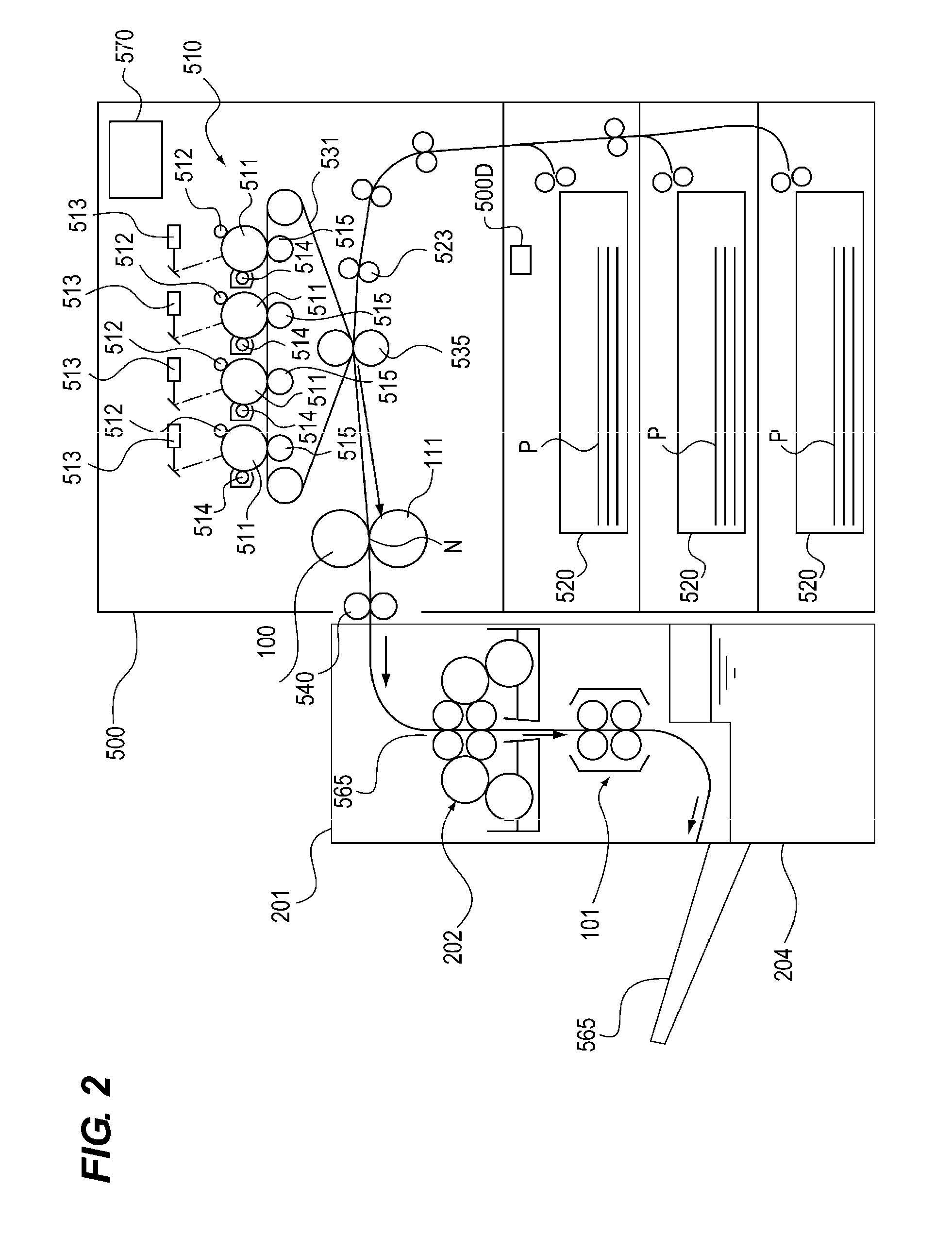
[0052]FIG. 2 is a cross-sectional view schematically illustrating a color electrophotographic printer 500 as an example of the image forming apparatus which is taken along a conveying direction of a sheet. Herein, the color electrophotographic printer will be simply referred to as a “printer”.

[0053]The sheet is used to form a toner image thereon. Specific examples of the sheet include plain paper, a resin sheet-like medium as a substitute for the plain paper, thick paper, a medium used for an overhead projector, and the like.

[0054]The printer illustrated in FIG. 2 includes an image forming portion 510 of each color of Y (yellow), M (magenta), C (cyan), and Bk (black). The image forming portion 510 of each color is used to form a toner image of each color on the sheet. The image forming portion 510 of each color includes process portions as follows; an electrophotographic photoconducto...

second embodiment

[0141]The configuration of the sheet pulling and conveying apparatus according to the embodiment will be described using FIGS. 17 to 19. FIG. 17 is a top view illustrating the sheet pulling and conveying apparatus 101 used in the embodiment. The embodiment is different from the first embodiment only in the sheet pulling and conveying apparatus 101, and thus the configurations overlapped with the first embodiment will not be repeated.

[0142]In the above-mentioned embodiment, as the load portion, the electromagnetic hysteresis brake (the electromagnetic brake) is exemplified in which the brake torque can be changed as the exciting current is changed. In this regard, as the load portion, the embodiment describes a configuration in which a plurality of torque limiters TL1 to TL3 is connected to the driving gear 104G2 of the first roller A104 through clutches CL2 to CL4. Then, the load controller performs control such that the clutches CL2 to CL4 are selectively connected or disconnected ...


PUM

PropertyMeasurementUnit
inner diameteraaaaaaaaaa
thicknessaaaaaaaaaa

Abstract

Provided is a sheet conveying apparatus which can improve rippling of a sheet. The sheet conveying apparatus which conveys the sheet includes an electromagnetic hysteresis brake 131 which is configured to apply a tension force in a conveying direction of the sheet and a controller 500C which performs control on the electromagnetic hysteresis brake 131 to vary a load. The controller 500C performs control on the load of the electromagnetic hysteresis brake 131 according to information relating to the sheet.

Description

BACKGROUND OF THE INVENTION[0001]1. Field of the Invention[0002]The present invention relates to a sheet conveying apparatus which conveys a sheet and suppresses rippling or curls of the sheet, and an image forming apparatus which includes the sheet conveying apparatus.[0003]2. Description of the Related Art[0004]In the related art, an image forming apparatus which employs an electrophotographic system develops a latent image formed on a photosensitive drum serving as an image bearing member so as to be a visible image, and then transfers the visible image (a toner image) onto the sheet using an electrostatic force. Next, the toner image on the sheet is fixed by heat and pressure, and an image is recorded on the sheet.[0005]As for a fixing apparatus of such an image forming apparatus, a heat roller fixation system is employed. In the heat roller fixation system, a fixing roller is kept in a predetermined temperature using a heat source such as a heater provided therein, an elastic p...

Claims


Application Information

Patent Timeline
Patent Type & Authority Applications(United States)
IPC IPC(8): B65H7/06B65H5/06
CPCB65H5/062B65H7/06B65H29/125B65H2301/51252B65H2301/5142B65H2403/724B65H2403/7254B65H2403/732B65H2515/805B65H2801/27G03G15/6573G03G15/6576G03G2215/00662G03G2215/0067B65H2404/131B65H2220/09B65H2515/10B65H2515/32B65H2220/01B65H2220/02
Inventor TAKEMATSU, KOJIOKUDA, KAZUHISASUGAYA, KENJIRO
Owner CANON KK
Why Eureka
Try Eureka