Electromagnetic device and conductive structure thereof

a technology of electromagnetic devices and conductive structures, applied in the direction of transformer/inductance details, basic electric elements, coils, etc., can solve the problems of increasing costs, fluid leakage, damage to electromagnetic devices, etc., and achieve the effect of improving the heat dissipation ability of electromagnetic devices

Active Publication Date: 2015-04-30
DELTA ELECTRONICS (SHANGHAI) CO LTD
View PDF9 Cites 6 Cited by
  • Summary
  • Abstract
  • Description
  • Claims
  • Application Information

AI Technical Summary

Benefits of technology

[0008]One aspect of the present disclosure is to improve the heat dissipation ability of the electromagnetic device.
[0012]In the foregoing conductive structure, protrusions are disposed on the conductive sheet. As such, the contacting surface that the conductive structure contacts with the airflow may not be planar and may be uneven, which may effectively improve the heat dissipation ability.

Problems solved by technology

However, the electromagnetic device inevitably produces heat energy during operation.
In addition to the liquid cooling plate, the accessories, such as the circulation fluid tank, the circulation pump, the heat exchanger and the pipes, are required as well, which increase the cost.
Moreover, lots of joints exist in the circulation path of the fluid, and therefore, the fluid may leak and damage the electromagnetic device.
As a result, due to the limit of the surface area of the winding, the heat ability of the air cooling is limited, which is difficult to satisfy the requirement of the heat dissipation ability of the high power electromagnetic device.

Method used


Image

  • Electromagnetic device and conductive structure thereof
  • Electromagnetic device and conductive structure thereof
  • Electromagnetic device and conductive structure thereof

Examples


Embodiment Construction

[0029]Reference will now be made in detail to the present embodiments of the invention, examples of which are illustrated in the accompanying drawings. Wherever possible, the same reference numbers are used in the drawings and the description to refer to the same or like parts. However, the details disclosed below may not be all essential or necessary, and are not for limitation of present invention.

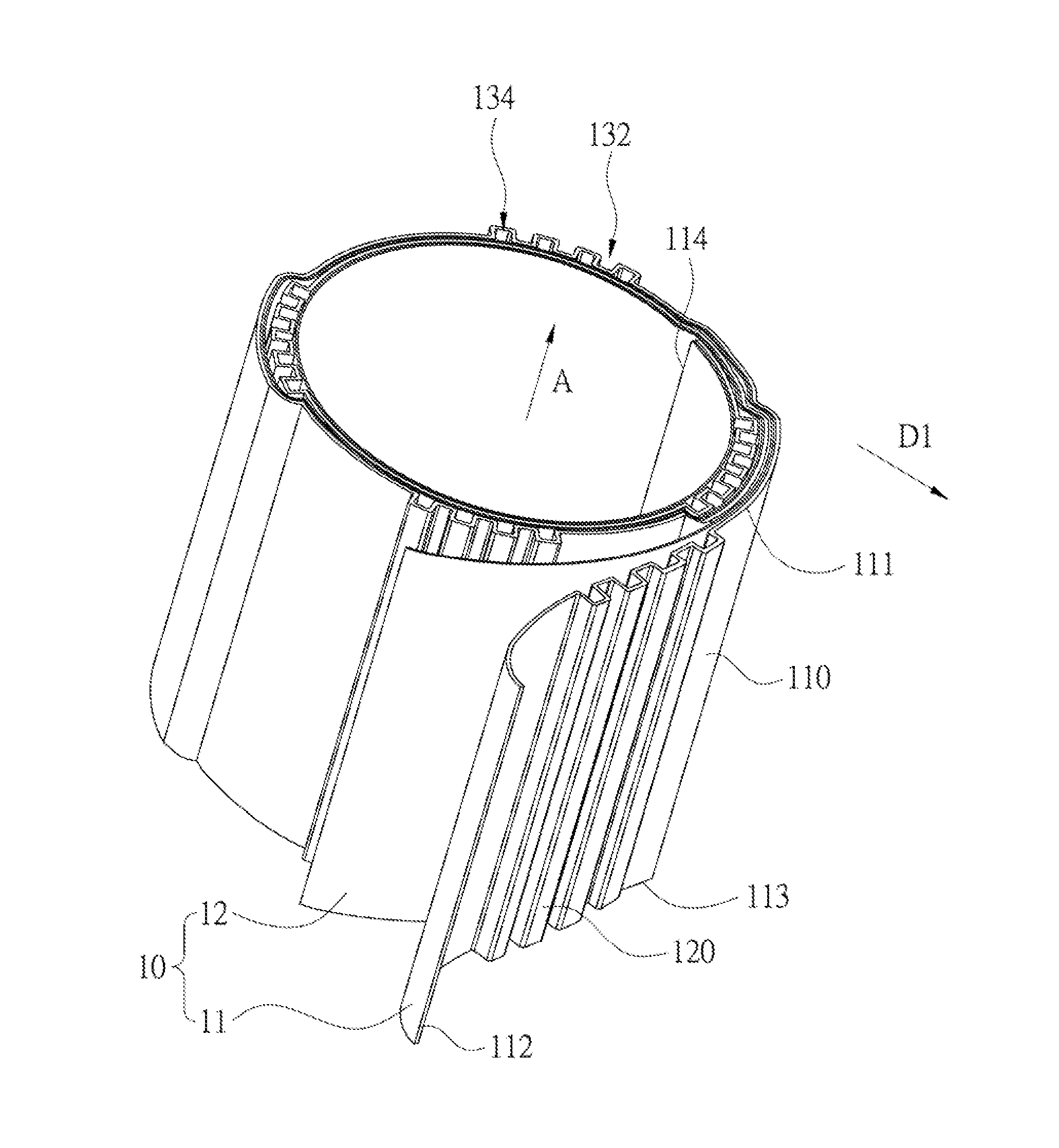
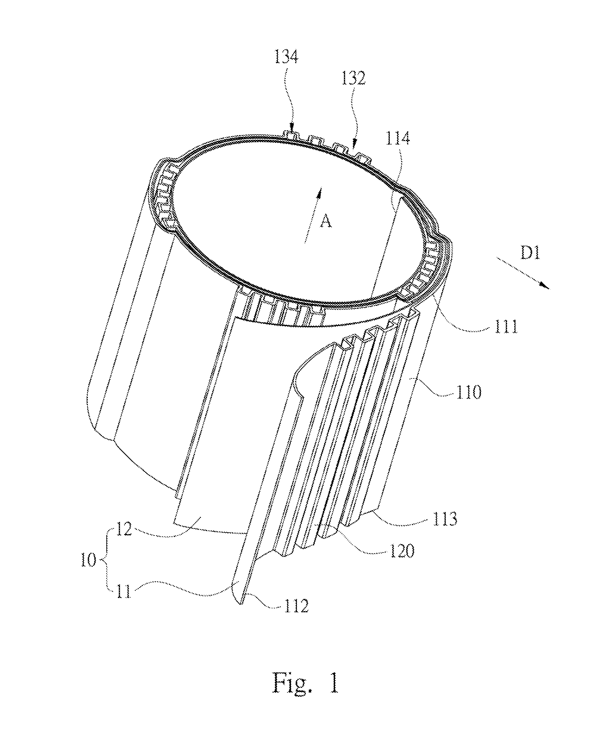
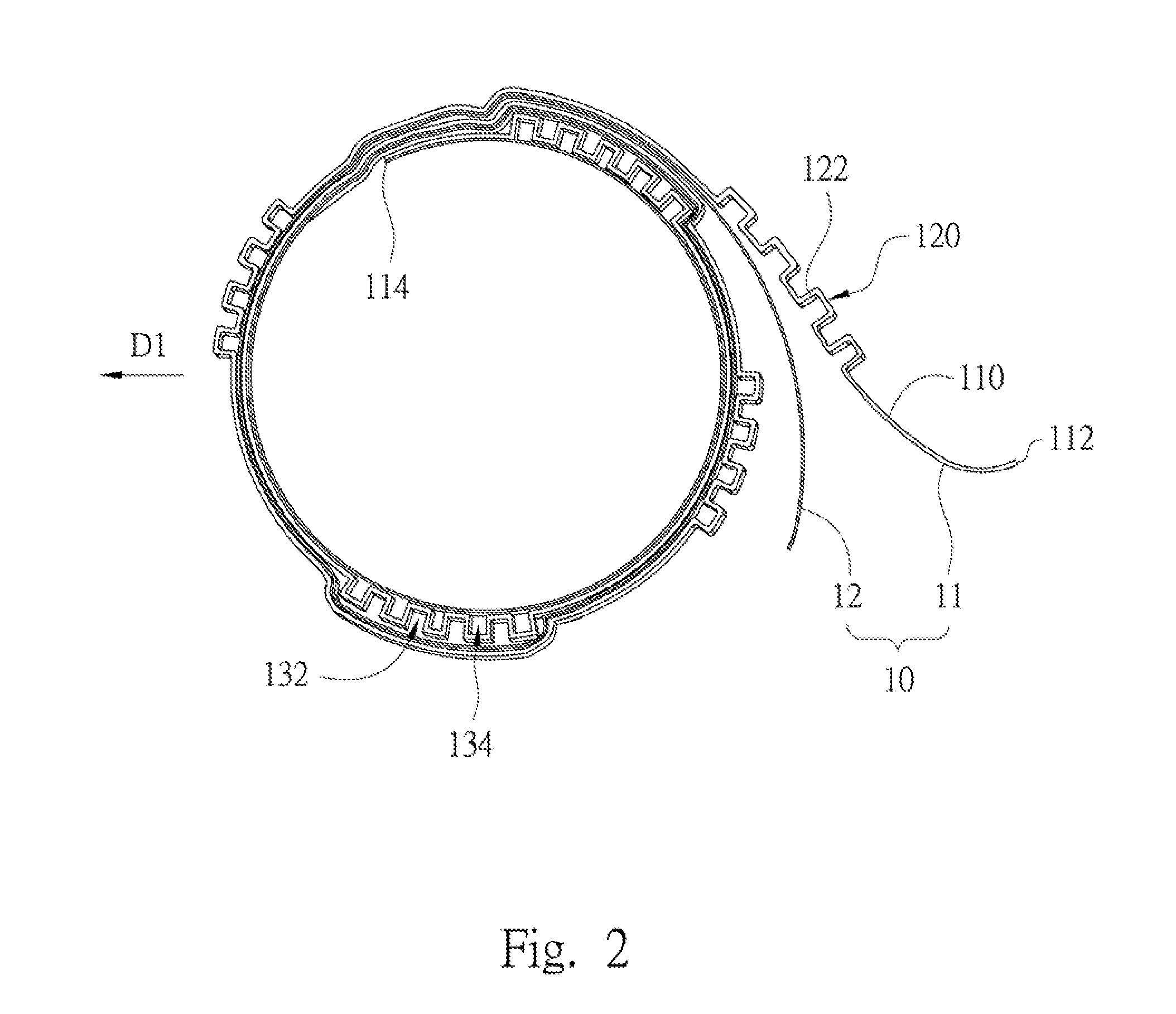
[0030]FIG. 1 is a perspective view of the electromagnetic device in accordance with one embodiment of the present disclosure. FIG. 2 is a top view of the electromagnetic device in FIG. 1. As shown in FIGS. 1 and 2, the electromagnetic device includes a winding 10. The winding 10 includes a conductive structure 11. The conductive structure 11 includes a conductive sheet 110 and a plurality of protrusions 120. The conductive sheet 110 has two electrical connection terminals 112 and 114 for connecting external electric devices. The protrusions 120 are disposed on the conductive sheet 110. E...


PUM

PropertyMeasurementUnit
conductiveaaaaaaaaaa
areaaaaaaaaaaa
magneticaaaaaaaaaa

Abstract

A conductive structure for an electromagnetic device includes a conductive sheet and a plurality of protrusions. The conductive sheet includes two electrical connection terminals. The protrusions are arranged between the electrical connection terminals. The protrusions include a support. The support is connected to the conductive sheet. Adjacent two of the protrusions define a first heat dissipation passage.

Description

RELATED APPLICATIONS[0001]This application claims priority to China Application Serial Number 201310522211.7, filed Oct. 29, 2013, which is herein incorporated by reference.BACKGROUND[0002]1. Technical Field[0003]Embodiments of the present invention relate to an electromagnetic device. More particularly, embodiments of the present invention relate to an electromagnetic device and the conductive structure thereof.[0004]2. Description of Related Art[0005]Electromagnetic device is one of the key components in the electricity system. For example, the electromagnetic device, such as the electric reactor and the transformer, has been widely applied in various electricity systems. However, the electromagnetic device inevitably produces heat energy during operation. In order to make the electromagnetic device work normally without being affected by the heat energy, various heat dissipation techniques are employed.[0006]The heat dissipation technology generally includes the liquid cooling an...

Claims


Application Information

Patent Timeline
Patent Type & Authority Applications(United States)
IPC IPC(8): H01F7/20
CPCH01F2007/062H01F7/20H01F27/2847H01F27/2876H01F27/323
Inventor LIU, TENGTONG, AI-XING
Owner DELTA ELECTRONICS (SHANGHAI) CO LTD
Why Eureka
Try Eureka