Scaled video for pseudo-analog transmission in spatial domain
a pseudo-analog transmission and spatial domain technology, applied in the field of spatial domain scaled video for pseudo-analog transmission, can solve the problems of increasing bandwidth usage, choppy or stalled video reproduction at the receiver, not graceful, etc., and achieve the effect of reducing the bandwidth used to transmit, reducing bandwidth usage, and maintaining a bandwidth budg
- Summary
- Abstract
- Description
- Claims
- Application Information
AI Technical Summary
Benefits of technology
Problems solved by technology
Method used
Image
Examples
example environment
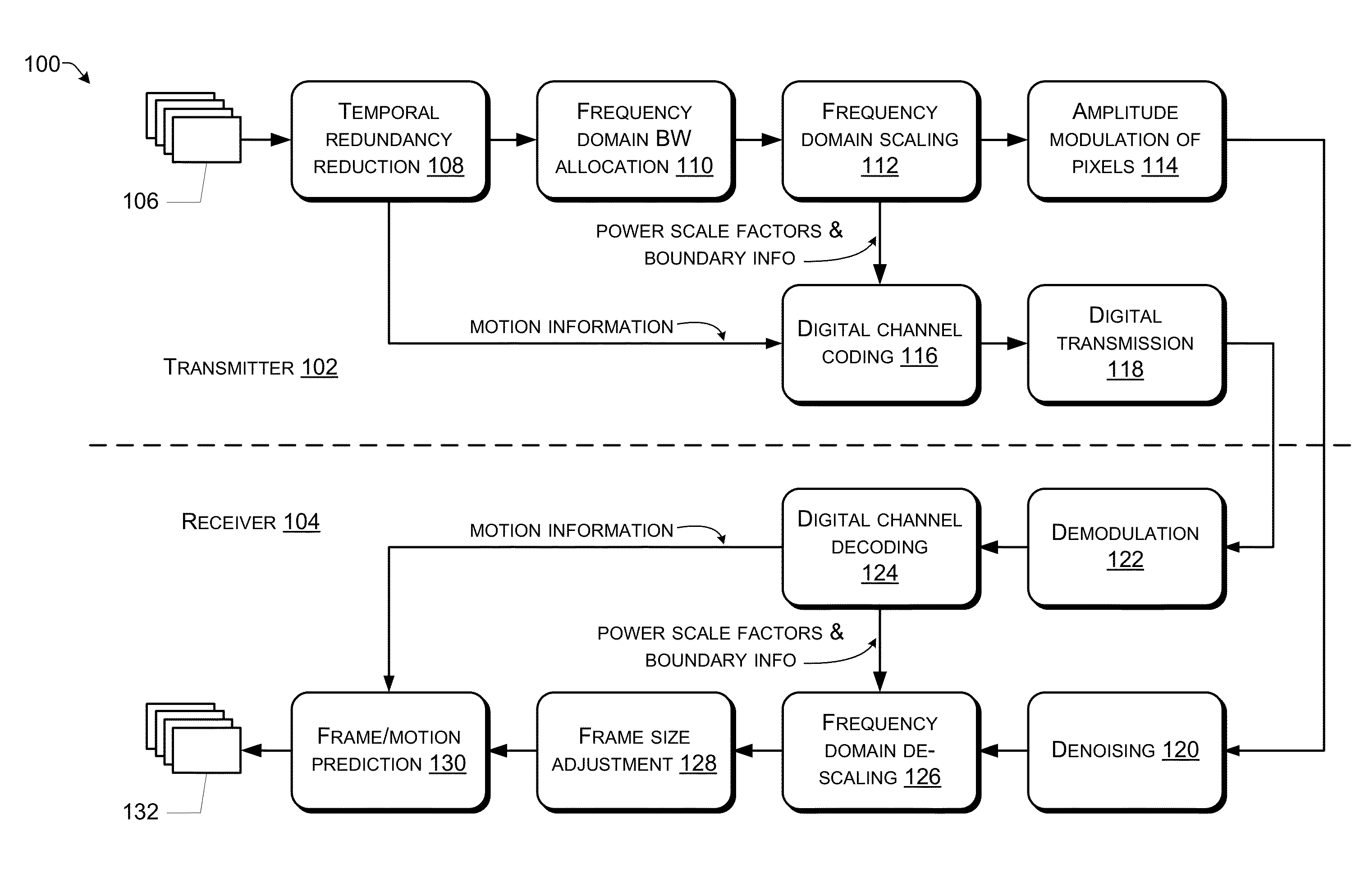
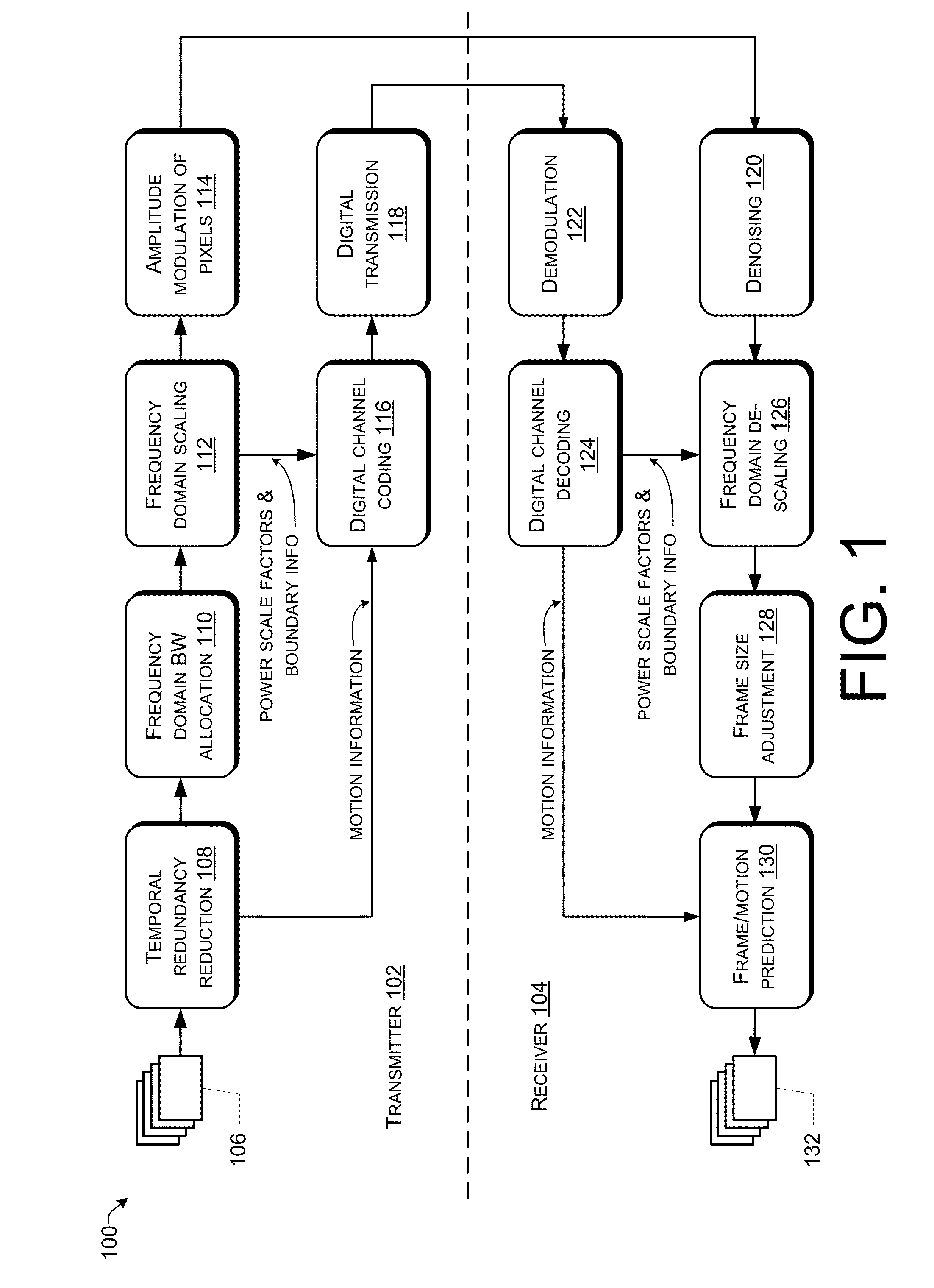
[0018]FIG. 1 is a block diagram of an example environment 100 for transmitting power-scaled video in the spatial domain via pseudo-analog transmission. A transmitter 102 is configured to be in communication with a receiver 104 to transmit video, such as real-time video. In real-time video, the transmission is modified to fit into a bandwidth budget that enables the video to be displayed at the receiver as it is received. An original group of pictures (GOP) 106 represents a set of contiguous or adjacent video frames of an overall video transmission. The video frames in the GOP 106 may include, according to various embodiments, various numbers of frames, but typical GOPs include 4, 8, 16, or other number of video frames.
[0019]Temporal redundancy reduction 108 is performed on the video frames of the GOP 106 in order to remove temporal redundancy between the frames. An open-loop prediction method is used, such as motion-compensated temporal filtering (MCTF) as is discussed in more detai...
example transmitter
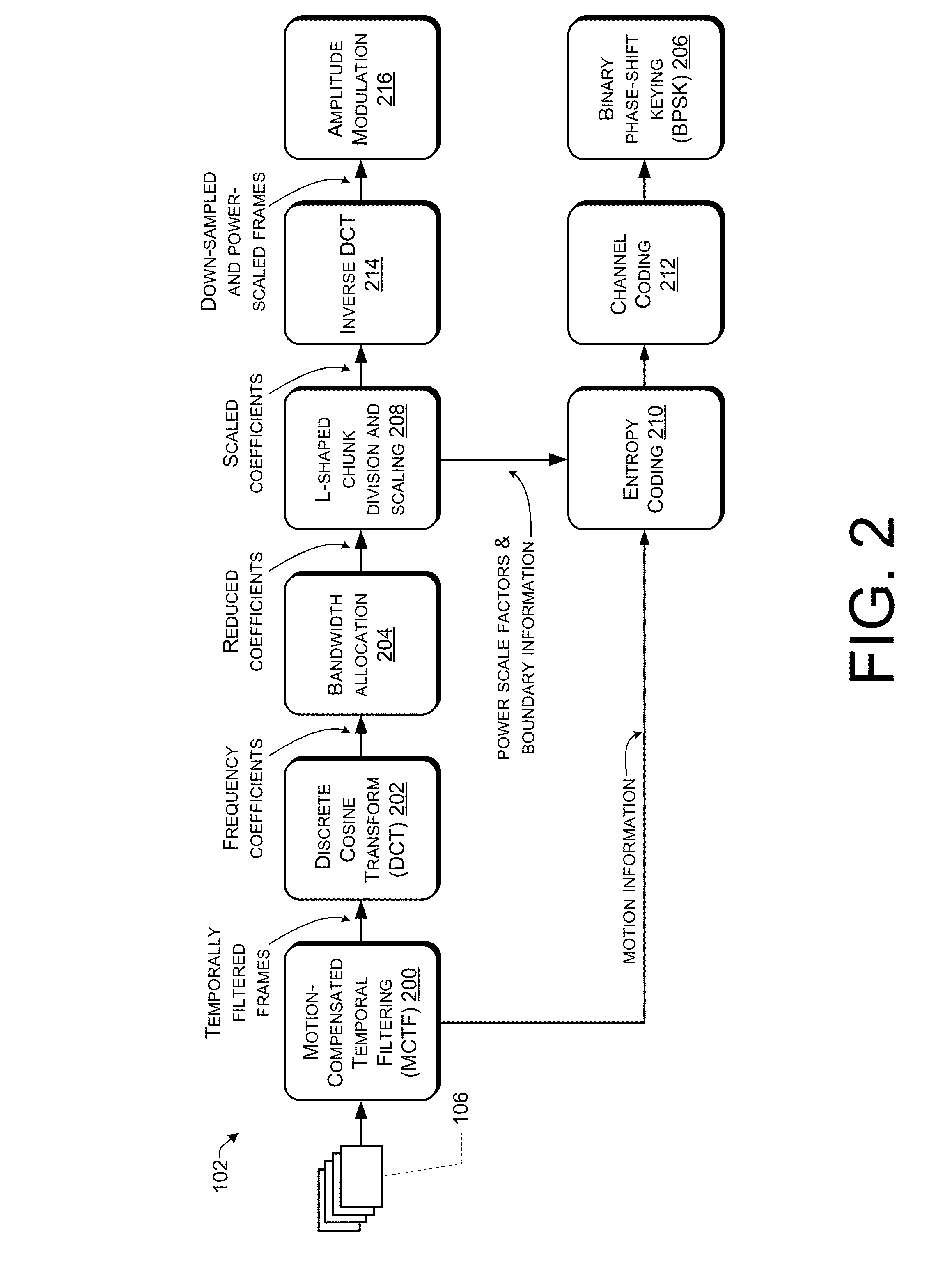
[0031]FIG. 2 is a block diagram of an example transmitter 102 configured to transmit power-scaled video in the spatial domain via pseudo-analog transmission. FIG. 2 illustrates various embodiments of the transmitter 102 in more detail.
[0032]MCTF 200, which is performed on the GOP 106 to produce temporally filtered frames, is described in more detail below with respect to FIG. 5. DCT 202 is performed on the temporally filtered frames to produce frequency coefficients.
[0033]Bandwidth allocation 204 is performed in the frequency domain. Bandwidth ratio, denoted by p, is defined as the ratio of channel bandwidth to source bandwidth. In embodiments of the present disclosure, the digital transmission of motion information will occupy a certain portion of the available bandwidth. The exact amount can be computed from the result of entropy coding. When Binary Phase Shift Keying (BPSK) 206 is used, each entropy coded bit may take two complex symbols to transmit. The remai...
example receiver
[0043]FIG. 4 is a block diagram of an example receiver 104 configured to receive power-scaled video in the spatial domain via pseudo-analog transmission. FIG. 4 illustrates embodiments of the receiver 104 in more detail.
[0044]Denoising 400 is performed on the received pixel values of frames of a GOP, received on a pseudo-analog signal. Source redundancy can provide channel protection under the premise that it is utilized at the receiver. Denoising is applied to channel output (e.g., to the received signals as they are received). The denoising processes for low-pass and high-pass frames are identical. Denoising 400 uses different denoising techniques to deal with packet losses and random-valued noises. In particular, a median filter is used to handle packet losses. Under ideal interleaving, packet loss creates randomly dispersed pixel “holes” in the frame. These holes are filled with the median of surrounding eight (or other number of) pixel values. More advanced median filters, such...
PUM
 Abstract
Description
Claims
Application Information
 - R&D
- Intellectual Property
- Life Sciences
- Materials
- Tech Scout
- Unparalleled Data Quality
- Higher Quality Content
- 60% Fewer Hallucinations
Browse by: Latest US Patents, China's latest patents, Technical Efficacy Thesaurus, Application Domain, Technology Topic, Popular Technical Reports.
© 2025 PatSnap. All rights reserved.Legal|Privacy policy|Modern Slavery Act Transparency Statement|Sitemap|About US| Contact US: help@patsnap.com


