Wind Turbine, its Use and a Vane for Use in the Turbine

Active Publication Date: 2015-04-30
JOOSTEN WILHELMUS HELENA HENDRIKUS
View PDF19 Cites 13 Cited by
  • Summary
  • Abstract
  • Description
  • Claims
  • Application Information

AI Technical Summary

Benefits of technology

[0012]The present invention also pertains to the use of a wind turbine as defined here-above for converting wind into work. The invention also pertains to a combination of the present turbine with a Darrieus wind mill, the wind turbine being operatively connected to the Darrieus wind mill, wherein the operative connection uses a clutch that allows that the wind turbine to rotate at various revelations per minute for a predetermined number of revelations per minute for the Darrieus wind mill. In this combination, the wind turbine may be used to start the Darrieus mill. Since the present turbine will start to revel

Problems solved by technology

This means that this receptacle negatively converts wind energy into motion of the turbine.
Also, due to the fact that the receptacle may be forced to activ

Method used


Image

  • Wind Turbine, its Use and a Vane for Use in the Turbine
  • Wind Turbine, its Use and a Vane for Use in the Turbine
  • Wind Turbine, its Use and a Vane for Use in the Turbine

Examples


examples

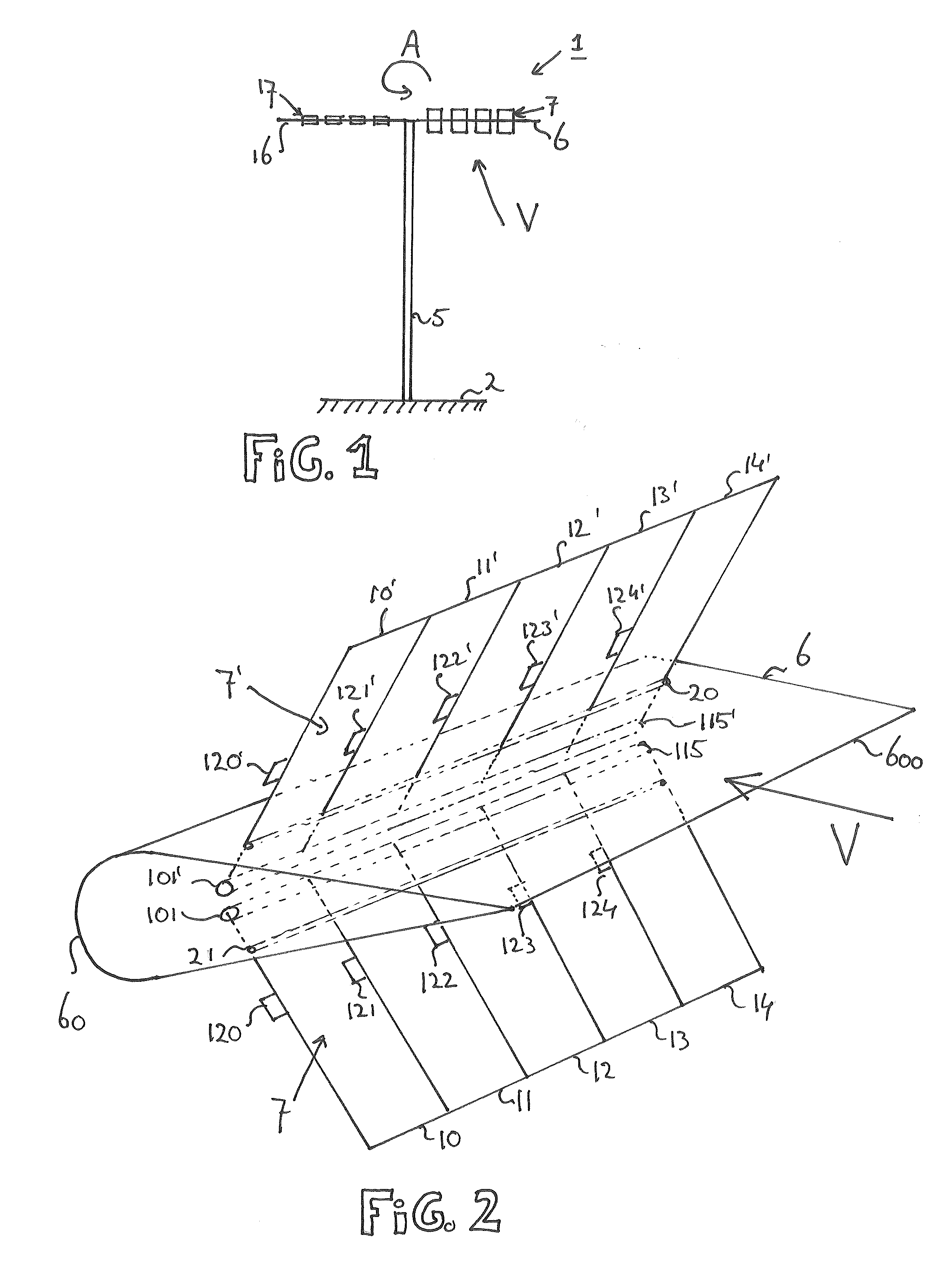
[0031]FIG. 1 is a schematic representation of a wind turbine according to the invention.

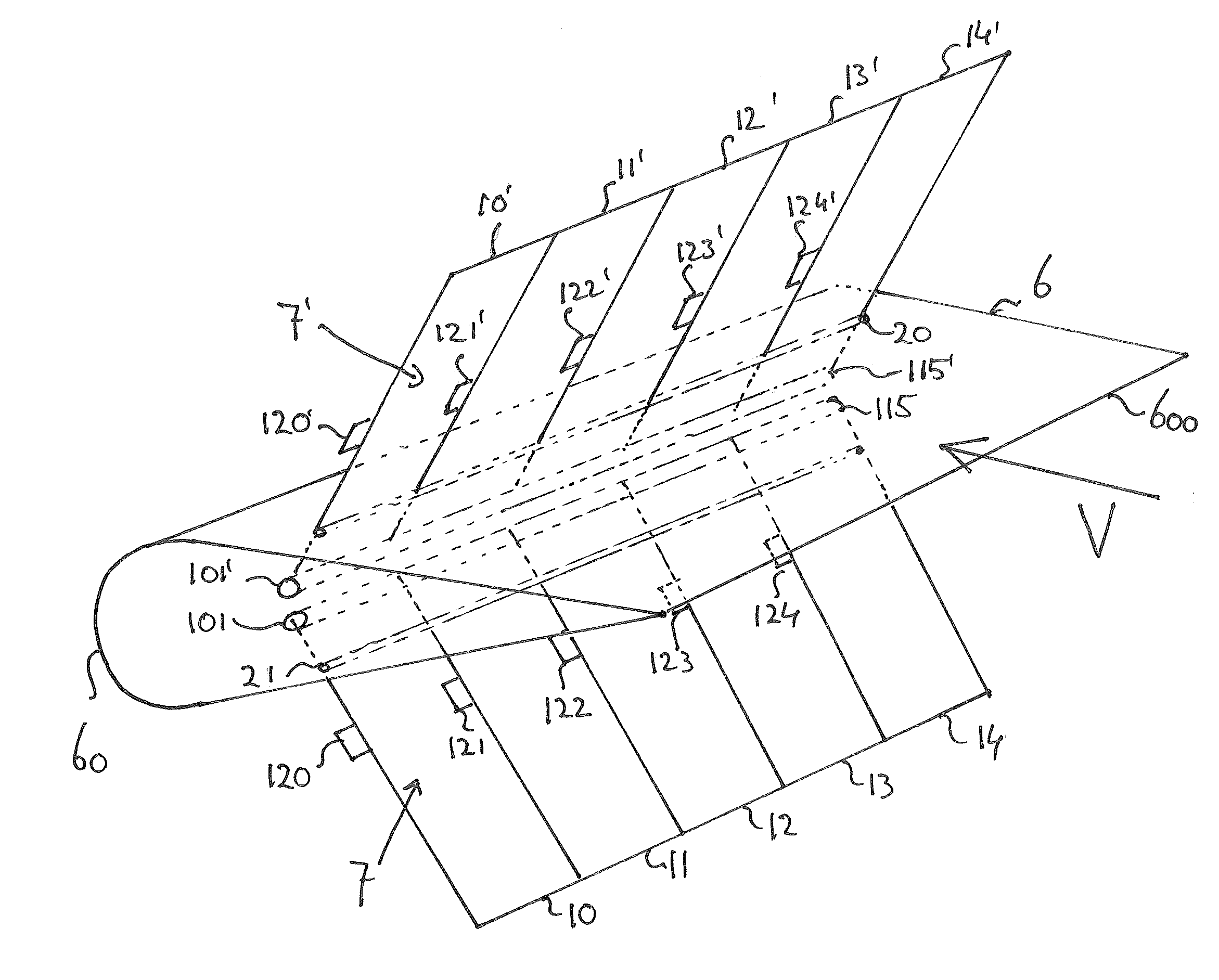
[0032]FIG. 2 is a schematic representation of a vane according to the invention.

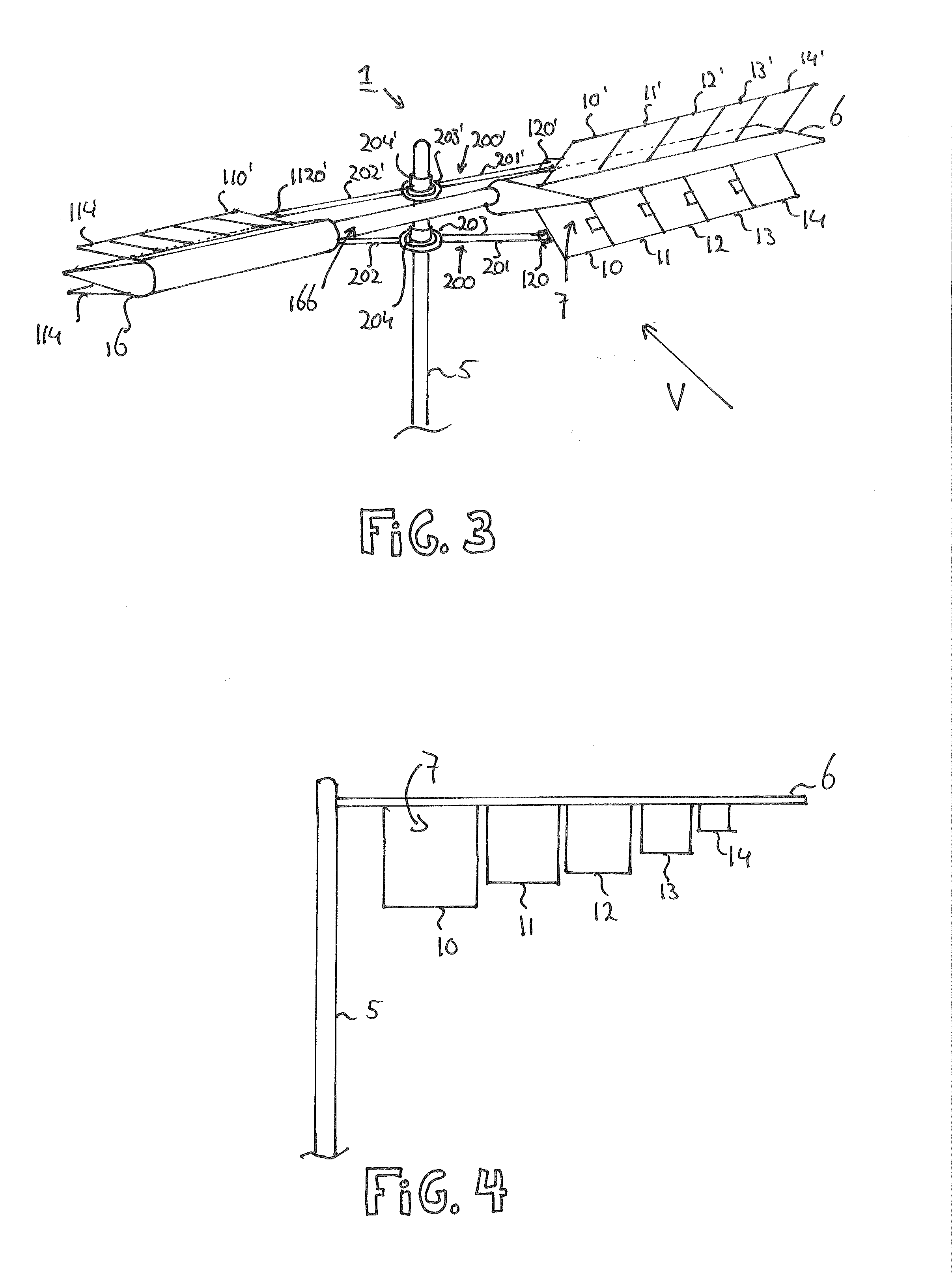
[0033]FIG. 3 is a schematic representation of a wind turbine according to the invention, comprising two vanes and depicting means operable to force the receptacle to adopt the second configuration.

[0034]FIG. 4 is a schematic representation of an alternative embodiment of a turbine according to the invention.

[0035]FIG. 5 schematically depicts various receptacles for use in the present invention.

[0036]FIG. 6 schematically depicts a combination of two wind turbines according to the invention with a Darrieus wind mill.

[0037]FIG. 7 illustrates the capacity of a receptacle to convert wind force into motion.

[0038]FIG. 8 schematically represents a system for providing the configurations of wind receptacles.

[0039]FIG. 1

[0040]FIG. 1 is a schematic representation of a wind turbine according to the invention. Depicted is a turbin...


PUM


Abstract

A wind turbine for converting wind into mechanical energy, includes a support and a vane rotatably connected to the support, the vane including a wind receptacle that can adopt a first configuration when the vane is in a position to travel in the direction of the wind, in which first configuration the receptacle has a first capacity to convert wind force into motion of the vane, and a second configuration when the vane is in a position to travel against the direction of the wind, in which second configuration the receptacle has a second capacity to convert wind force into motion of the vane, the second capacity being lower than the first capacity, wherein the turbine is provided with an arrangement that is operable to force the receptacle to adopt at least one of the configurations independent from the direction of the wind.

Description

FIELD OF THE INVENTION[0001]The present invention pertains to a wind turbine for converting wind into mechanical energy, comprising a support and a vane rotatively connected to said support, the vane comprising a wind receptacle that can adopt a first configuration when the vane is in a position to travel in the direction of the wind, in which first configuration the receptacle has a first capacity to convert wind force into motion of the vane, and a second configuration when the vane is in a position to travel against the direction of the wind, in which second configuration the receptacle has a second capacity to convert wind force into motion of the vane, the second capacity being lower than the first capacity. The invention also pertains to the use of the wind turbine for converting wind into work, and to a vane for use in the wind turbine.BACKGROUND OF THE INVENTION[0002]Wind turbines are commonly used since centuries to convert wind into work. A wind turbine typically is an imp...

Claims


Application Information

Patent Timeline
IPC IPC(8): F03D3/06F03D3/02F03D11/02F03D3/00
CPCF03D3/068F03D11/02F03D3/02F03D3/005Y02E10/74F05B2240/212F05B2240/218F03D15/00
Inventor JOOSTEN, WILHELMUS HELENA HENDRIKUS
Owner JOOSTEN WILHELMUS HELENA HENDRIKUS
Why Eureka
Try Eureka