
Wind turbine blade and blade hub

a technology of wind turbine blades and blade hubs, which is applied in the direction of renewable energy generation, vessel construction, greenhouse gas reduction, etc., can solve the problems of exclusive (expensive) equipment and manufacturing techniques, and achieve the effect of reducing torque ripple driven vibration stress and less stressful blade deflection vibration frequency

Inactive Publication Date: 2015-03-26
BARNES ROBERT JEFFREY
View PDF12 Cites 8 Cited by
  • Summary
  • Abstract
  • Description
  • Claims
  • Application Information

AI Technical Summary

Benefits of technology

This patent text describes a vertical axis wind turbine with a four blade rotor design that has several technical advantages. The rotor is made of a hollow circular cylindrical aluminum alloy tower, four single length aluminum alloy blade extrusions, and four stackable blade hubs. The blade hubs are made of interlocking L-shaped cross section beams that provide stability to the rotor. The design reduces torque ripple driven vibration stresses, and allows for lighter and longer-lasting blade sections, resulting in lower centrifugal blade forces and higher vibration frequencies. The cost-effective design uses practical commercial and industrial power conversion ratings, and is capable of withstanding high winds while in a fully installed condition. The rotor also uses a pivot erection installation method and a unique hub design that eliminates expensive extension joints and allows for thinner and more resistant blade sections. Middle length blade braces enhance wind survivability, and the rotor can have a maximum power conversion rating of 75 or 100 HP, depending on the design.

Problems solved by technology

The 34-Meter Test Bed also represented the anxiety of the 1980s, “to build it big”, with the most exclusive (expensive) equipment and manufacturing techniques.

Method used


Image

  • Wind turbine blade and blade hub
  • Wind turbine blade and blade hub
  • Wind turbine blade and blade hub

Examples


Embodiment Construction

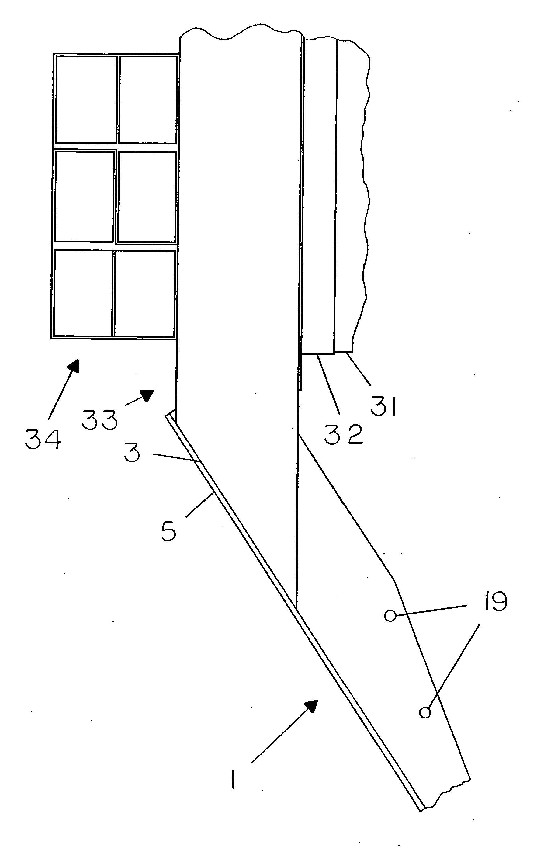
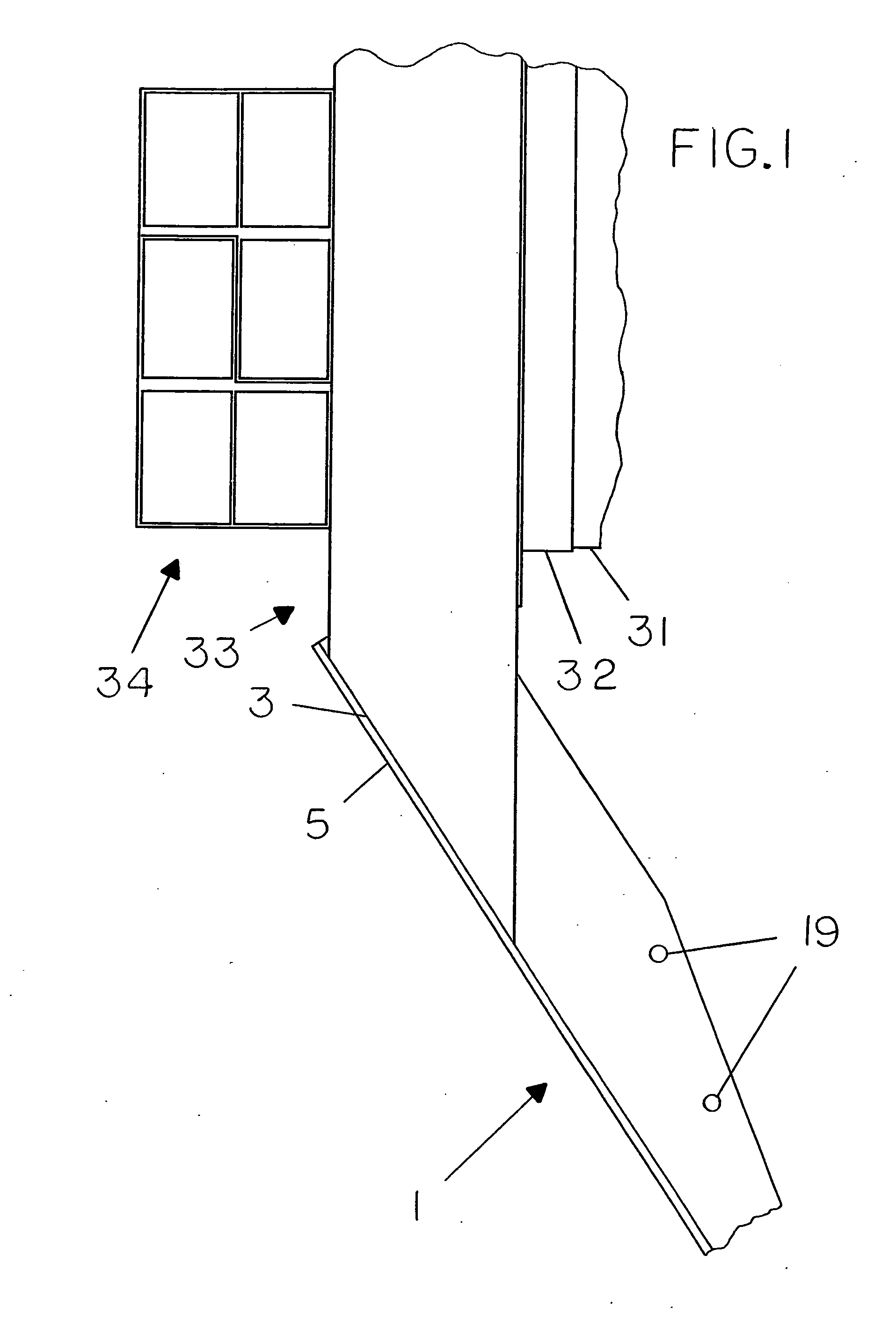
[0032]FIG. 1 shows a side view of a four blade 75 horsepower VAWT rotor lower blade hub stack. Inside lower hub assembly 33 is shown in FIG. 1. Inside blade extrusion 1 is shown mounted to inside hub assembly 33 in FIG. 1. Inside hub assembly 33 is cut off for the hub end opposite blade extrusion 1. The side of the hollow cylindrical rotor tower 31 is shown mounted to inside hub 33 by 2 flange ring 32 in FIG. 1. Tower. 31 is bolted to one flange of ring 32. Hub 33 is bolted to the other flange of ring 32. The bolts for 2 flange ring 32 are not shown. Tower 31 and 2 flange ring 32 are shown cut off with a jagged line. The hollow end of outside lower rotor hub assembly 34 is shown attached to inside rotor hub assembly 33 in FIG. 1. Blade extrusion 1 tail edge 3 is shown in FIG. 1. Blade extrusion 1 outside peak curve line 5 is shown in FIG. 1. Blade extrusion 1 vibration tuning holes 19 are shown in FIG. 1. The center of the length of rotor tower 31 is off the right edge of FIG. 1.

[00...


PUM


Abstract

Four blade VERTICAL AXIS WIND TURBINE is disclosed. Four equally radially spaced fixed troposkein shaped rotor blades nearly eliminates rotor torque ripple. Reduced rotor torque ripple allows thinner skin hollow cross section blades that are lighter and have higher frequency and lower stress natural vibrations. Improved single length blade extrusion has two integral mounting flanges at each of two root ends. One blade root flange is adjoined to the blade nose tip through a blade skin thickening gusset rail. One blade root flange is adjoined to the blade tail tip through a second blade skin thickening gusset rail. A third blade root flange forms a largely rectangular hollow between the two mounting flanges and the blade skin.A separable rectangular cross section blade hub is made from two hollow rectangular L-shaped cross section extruded beams. These L-shaped beams are cut from a single extrusion.

Description

CROSS REFERENCE TO RELATED APPLICATIONS[0001]Not Applicable:STATEMENT REGARDING FEDERALLY SPONSORED RESEARCH OR DEVELOPMENT[0002]Not Applicable:SEQUENCE LISTING[0003]Not Applicable:BACKGROUND OF THE INVENTION[0004]1. Field of the Invention[0005]This invention relates to vertical axis wind turbines which are used to convert wind energy.[0006]2. Description of the Related Art[0007]The Darrieus-type vertical axis wind turbine (VAWT) having its rotating shaft traverse to the air stream, was patented by G. M. Darrieus in the United States in 1931, U.S. Pat. No. 1,835,018. The Darrieus-type vertical axis wind turbine is said to resemble an egg-beater with curved blades connected at both ends to the ends of the rotating shaft. Each blade of the turbine is symmetrical in cross section and is bent along the blade length to approximate the shape a perfectly flexible cable would assume when spun around a vertical axis. This bent blade length shape is represented by the Greek word “troposkein” ...

Claims


Application Information

Patent Timeline
Patent Type & Authority Applications(United States)
IPC IPC(8): F03D1/06
CPCF03D1/06F03D3/064F05B2240/212Y02E10/74Y02E10/72
Inventor BARNES, ROBERT JEFFREYBARNES, KAREN LYNN
Owner BARNES ROBERT JEFFREY
Learn More