
Fluid Regulating Valve

Inactive Publication Date: 2015-04-30
ENERGREEN AS (NO)
View PDF0 Cites 0 Cited by
  • Summary
  • Abstract
  • Description
  • Claims
  • Application Information

AI Technical Summary

Benefits of technology

The present invention provides a valve with a sealing mechanism between the stator and rotor that allows for a substantial sealing, even with small fluid leakage. The valve has a structure that reduces bearing friction, wear, and internal leakage, resulting in increased efficiency and power efficiency. The valve also has a balanced rotor that reduces radial deflection and allows for a smaller clearance between the stator and rotor, which further increases efficiency. The valve can be designed with an increased capability to withstand high fluid pressures and flows, reducing manufacturing costs. The interior space of the valve can be divided into an even or odd number of chambers, and the openings can be arranged in pairs radially opposite to each other to achieve a more even distribution of radial forces and facilitate manufacturing.

Problems solved by technology

Even though the previously known valves may be utilized at and adapted for harvesting of energy while regulating the fluid pressure and / or the fluid flow in different types of fluid distribution networks, there still remain disadvantages of the known arrangements.
A major disadvantage of the previous known valves is the comparatively low efficiency, i.e. that a comparatively large portion of the energy carried by the fluid is lost in the valve, before conversion to useable energy, such as electricity.
A further disadvantage is a considerable wear of the constructional parts, especially at high fluid pressures.

Method used


Image

  • Fluid Regulating Valve
  • Fluid Regulating Valve
  • Fluid Regulating Valve

Examples


example

[0071]Comparative calculations of the efficiency at a previously known valve and a valve according to the present invention has been carried out. Except the differences in balancing of the rotor both valves are essentially equal and comprises a rotor with an active rotor length of approx. 300 mm.

[0072]At the previously know valve, a clearance of 2 mm between the rotor and the stator is needed for compensating for the deflection of the unbalanced rotor. This clearance results in a leakage opening of approx. 300 mm×2 mm=600 mm2 between the high pressure side and low pressure side at each vane.

[0073]Calculations have been carried out for such a known valve when driven at a differential pressure of 5 bar, where the fluid pressure upstream of the device is 6 bar and downstream 1 bar. These calculations show that if the valve is driven with an input water flow of 80 litres per second, then the internal leakage from the high pressure side to the low pressure side of the rotor is approximat...


PUM


Abstract

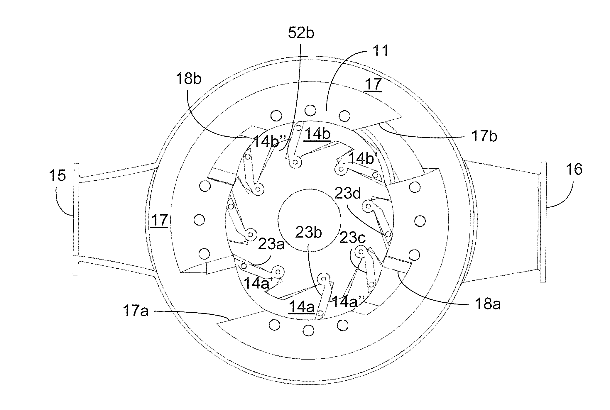
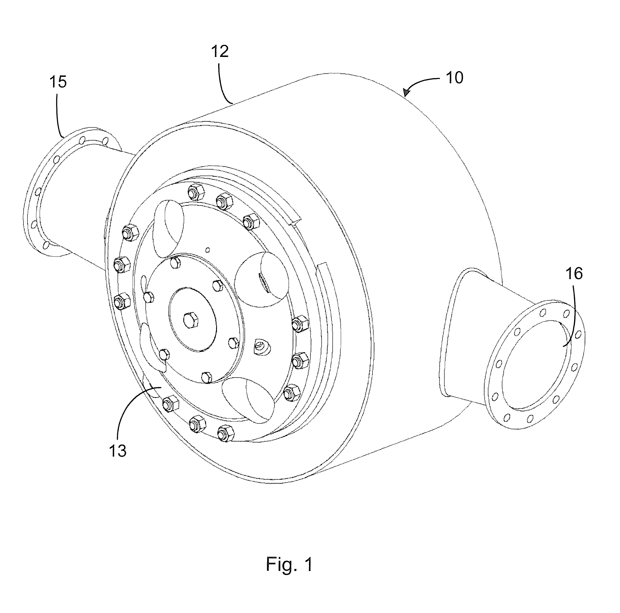
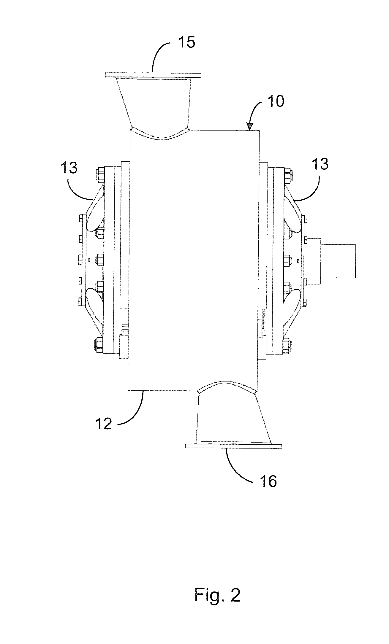
A valve for regulating the fluid pressure and / or the fluid flow in a fluid distribution network. The valve comprises a stator (10, 110) defining an interior space (14, 114); at least one inlet port (15, 131a, 132a) and at least one outlet port (15, 133a, 134a). The inlet port and outlet port are arranged for being connected to a fluid duct. A rotor (20, 120) is arranged rotatable about a rotational axis in the interior space and is provided with a rotor core (21, 121) and a number of vanes (23, 123), which are movable in relation to the core. The rotor continuously divides, in sealing relation with the stator, upon rotation of the rotor the interior space into at least two mutually separated chambers (14a, 14b, 114a-d). Each chamber comprises an inlet opening (17a, 17b, 112a) and an outlet opening (18a, 18b, 112b). The valve further comprises at least one inlet channel (17, 131, 132) which connects the at least one inlet port with at least one inlet opening of each of said at least two chambers and at least one outlet channel 18, 133, 134) which connects at least one outlet opening of each of said at least two chambers with the at least one outlet port

Description

TECHNICAL FIELD[0001]The invention relates to a valve for regulating the fluid pressure and / or the fluid flow in a fluid distribution and transportation network. In particular the invention relates to such a valve comprising a stator and a rotor arranged in the stator. The valve may be used to decrease the fluid pressure and / or flow, i.e. to produce a negative differential pressure or flow between the inlet port and the outlet port of the device by extracting power from the fluid. The rotor may be connected to a braking means for causing a decrease of the fluid pressure or the fluid flow.BACKGROUND AND PRIOR ART[0002]There often exists a need for regulating the fluid pressure and / or the fluid flow in fluid distribution networks. An example of such a fluid distribution network is a water distribution system used in cities for distributing drinking water from a central reservoir to a plurality of households and other water consumers. Such networks or systems typically comprise one or ...

Claims


Application Information

Patent Timeline
IPC IPC(8): F01C1/344F01C1/324
CPCF01C1/324F01C1/3446F03B13/00F03D9/00F05B2220/602Y02B10/30Y02B10/50Y02E10/72Y02B10/70Y02E10/20F01C1/344F01C13/00F03B17/06F16K11/085
Inventor MELHUS, TRONDSORENSEN, PER HASSEL
Owner ENERGREEN AS (NO)
Learn More