
System and Method for Analyzing Biological Signals and Generating Electrophyisology Maps

a biological signal and electrophysiology technology, applied in the field of electrophysiology mapping, can solve the problems of increasing the complexity of such procedures and the need to improve the quality of the electrophysiology map used

Active Publication Date: 2015-04-30
ST JUDE MEDICAL CARDILOGY DIV INC
View PDF2 Cites 24 Cited by
  • Summary
  • Abstract
  • Description
  • Claims
  • Application Information

AI Technical Summary

Benefits of technology

The patent describes a method and system for generating a cardiac electrophysiology map by aligning a reference biological signal with an electrical signal indicative of electrical activity at a location on a patient's heart. The reference biological signal can be a surface electrocardiogram, an intracardiac electrogram, a blood pressure signal, or any other biological signal that can be pathognomonic for an electrical event of interest. The system includes a graphical user interface processor and an electrophysiology mapping processor. The user interface processor receives the reference biological signal and the user's designation of a pair of trigger point icons on the reference biological signal. The trigger point icons define a plurality of triggering criteria, which can include an upward or downward threshold, a threshold-crossing time interval, and a reference biological signal amplitude. The electrophysiology mapping processor receives the electrical signal and adds an electrophysiology data point to the electrophysiology map only when the reference biological signal satisfies the defined triggering criteria. The system can also allow the user to redesign the triggering criteria and add or remove electrophysiology data points from the map. The generated cardiac electrophysiology map can be useful for diagnostic and therapeutic purposes.

Problems solved by technology

As the complexity of such procedures increases, however, the electrophysiology maps utilized must increase in quality, in density, and in the rapidity and ease with which they can be generated.

Method used


Image

  • System and Method for Analyzing Biological Signals and Generating Electrophyisology Maps
  • System and Method for Analyzing Biological Signals and Generating Electrophyisology Maps
  • System and Method for Analyzing Biological Signals and Generating Electrophyisology Maps

Examples


Embodiment Construction

[0023]The present disclosure provides methods, apparatuses and systems for the creation of electrophysiology maps (e.g., electrocardiographic maps). For purposes of illustration, several exemplary embodiments will be described in detail herein in the context of a cardiac electrophysiology procedure. It is contemplated, however, that the methods, apparatuses, and systems described herein can be utilized in other contexts.

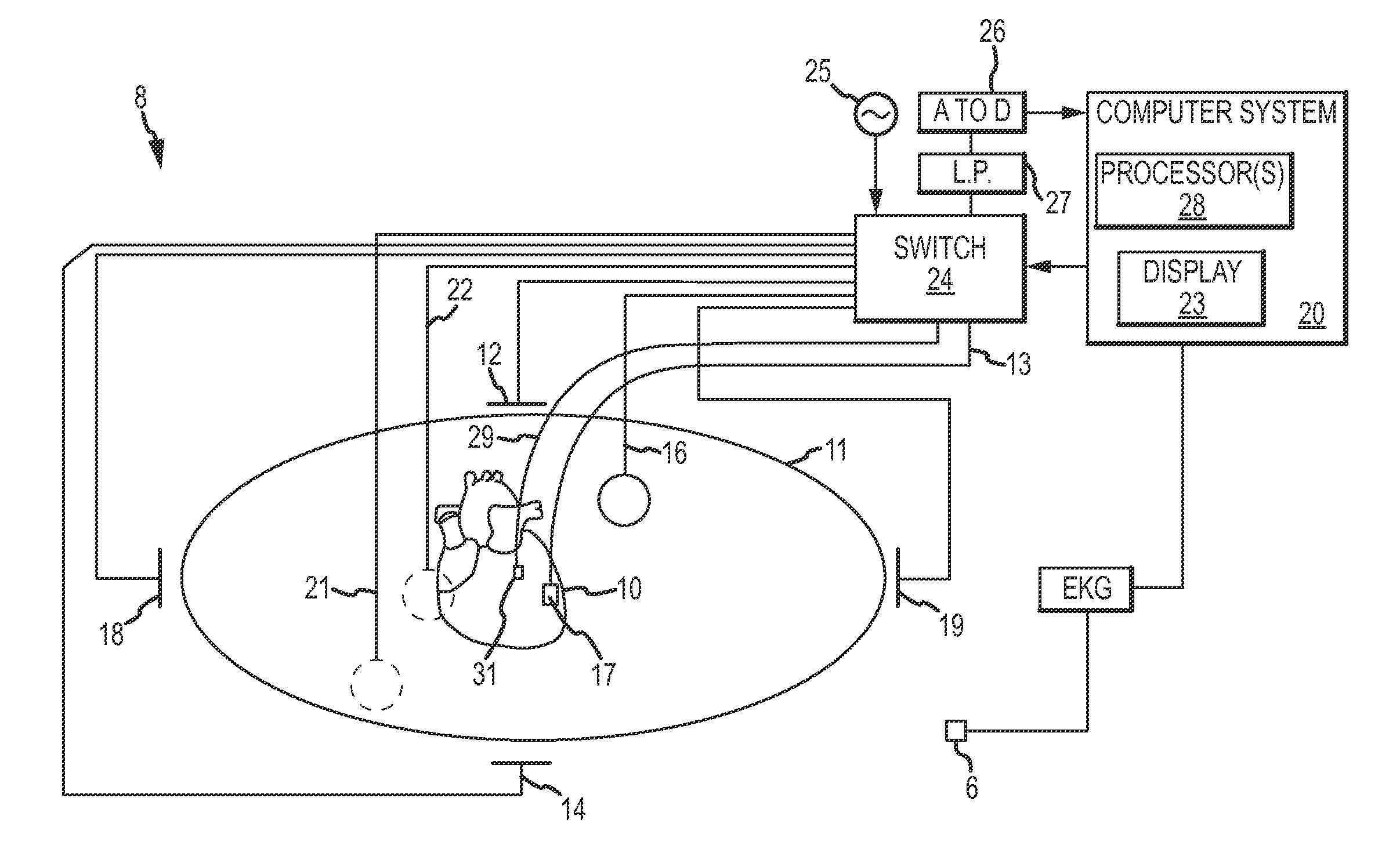
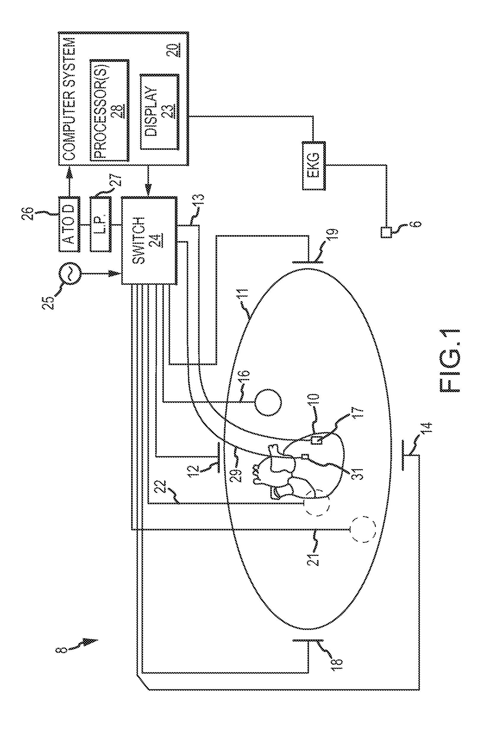
[0024]FIG. 1 shows a schematic diagram of an electrophysiology system 8 for conducting cardiac electrophysiology studies by navigating a cardiac catheter and measuring electrical activity occurring in a heart 10 of a patient 11 and three-dimensionally mapping the electrical activity and / or information related to or representative of the measured electrical activity. System 8 can be used, for example, to create an anatomical model of the patient's heart 10 using one or more electrodes. System 8 can also be used to measure electrophysiology data at a plurality of point...


PUM


Abstract

A method of generating a cardiac electrophysiology map includes receiving a reference biological signal and an electrical signal indicative of electrical activity at a location on a patient's heart. Using a graphical user interface, a practitioner designates at least two trigger point icons, one upward-pointing and one downward-pointing, on a graphical representation of the reference biological signal (e.g., a waveform). By pairing one upward-pointing icon with one downward-pointing icon, a plurality of triggering criteria are defined. Electrophysiology data points are captured and / or added to the electrophysiology map when the triggering criteria are satisfied.

Description

CROSS-REFERENCE TO RELATED APPLICATIONS[0001]This application claims the benefit of U.S. provisional application No. 61 / 897,863, filed 31 Oct. 2013, which is hereby incorporated by reference as though fully set forth herein.BACKGROUND[0002]The instant disclosure relates to electrophysiological mapping, such as may be performed in cardiac diagnostic and therapeutic procedures. In particular, the instant disclosure relates to systems, apparatuses, and methods for acquisition of signals and generating an electrophysiology map from data collected by an electrophysiology probe (e.g., a contact or non-contact mapping catheter).[0003]Electrophysiological mapping, and more particularly electrocardiographic mapping, is a part of numerous cardiac diagnostic and therapeutic procedures. As the complexity of such procedures increases, however, the electrophysiology maps utilized must increase in quality, in density, and in the rapidity and ease with which they can be generated.BRIEF SUMMARY[0004...

Claims


Application Information

Patent Timeline
IPC IPC(8): A61B5/04A61B5/0468A61B5/00A61B5/021A61B5/363A61B5/364
CPCA61B5/04012A61B5/7435A61B5/0468A61B5/021A61B5/743A61B5/283A61B5/287A61B5/363A61B5/316A61B5/364
Inventor DENO, DON CURTIS
Owner ST JUDE MEDICAL CARDILOGY DIV INC
Learn More