Steam Turbine Power Plant and Method for Activating Steam Turbine Power Plant

a steam turbine and power plant technology, applied in steam engine plants, boiler control, lighting and heating apparatus, etc., can solve the problems of low-cycle thermal fatigue accumulation in the turbine rotor, consumption amount, cracking of the turbine rotor, etc., and achieve the effect of safe activation

Active Publication Date: 2015-05-07
MITSUBISHI POWER LTD
View PDF0 Cites 10 Cited by
  • Summary
  • Abstract
  • Description
  • Claims
  • Application Information

AI Technical Summary

Benefits of technology

[0011]According to the invention, the steam turbine power plant can be safely activated at a high speed while

Problems solved by technology

Low-cycle thermal fatigue is accumulated in the turbine rotor, which is due to thermal stress generated in the turbine rotor during a cycle in which the activation of the steam turbine is stopped.
If the accumulated low-cycle thermal fatigue exceeds a limit of a material of the turbine rotor, a crack may occur in the turbine rotor.
However, in each of the activation modes, the numbers of times of the activation for one year may be different and the life consumption amounts of the turbine rotor for one time of the activation may be different between the time at

Method used


Image

  • Steam Turbine Power Plant and Method for Activating Steam Turbine Power Plant
  • Steam Turbine Power Plant and Method for Activating Steam Turbine Power Plant
  • Steam Turbine Power Plant and Method for Activating Steam Turbine Power Plant

Examples


first embodiment

Configuration

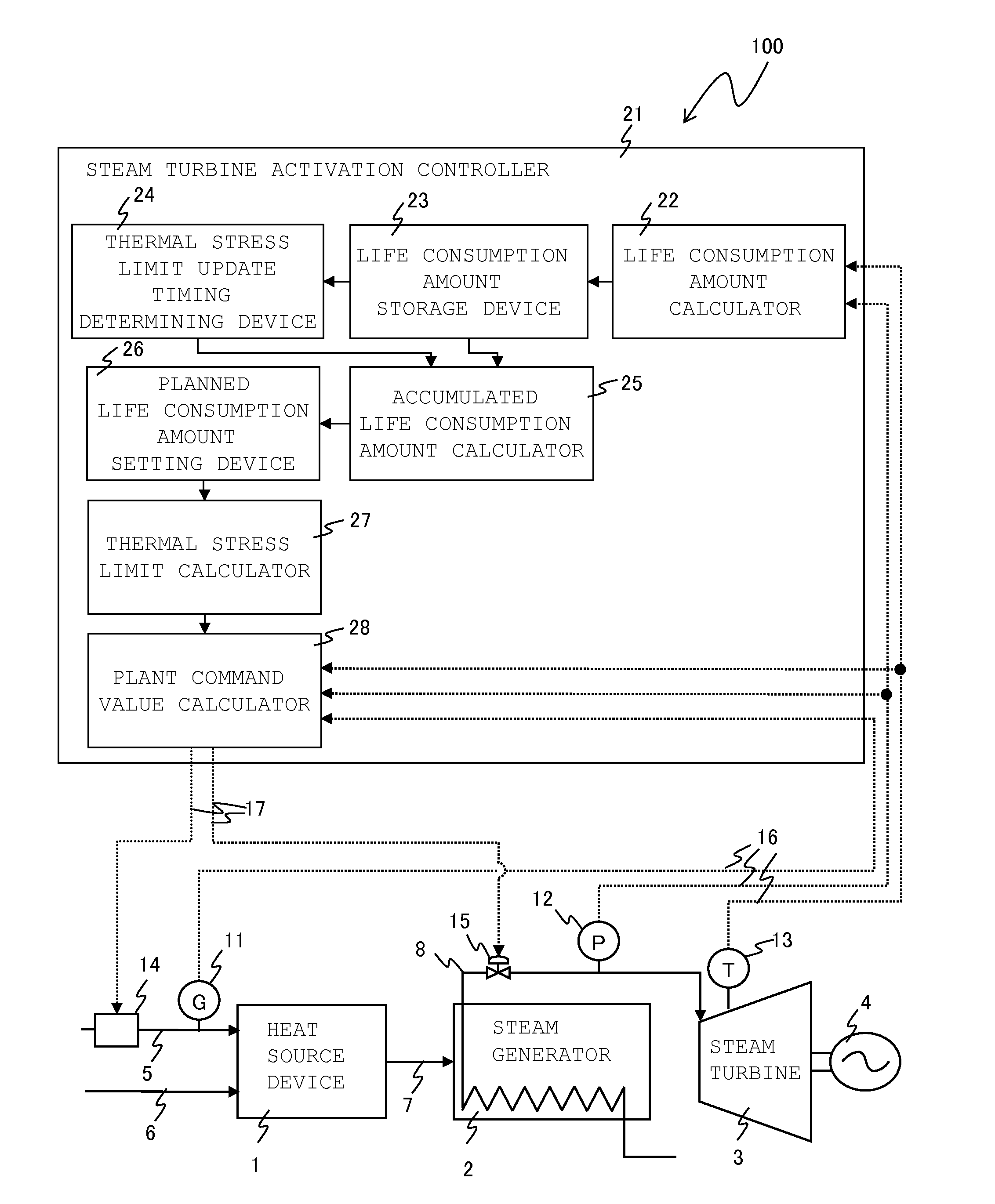
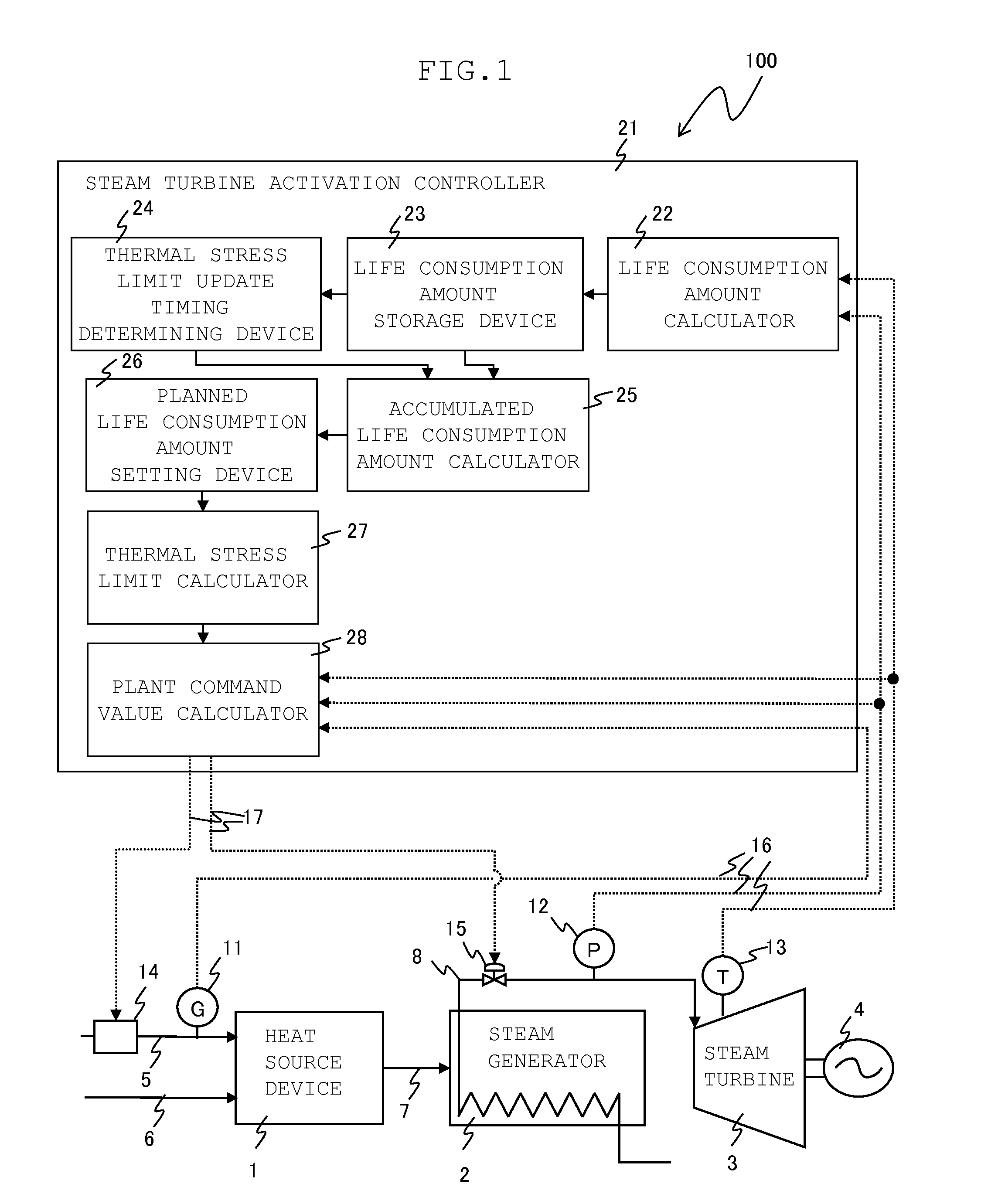
[0024]FIG. 1 is a schematic diagram illustrating a configuration of a steam turbine power plant 100 according to a first embodiment of the invention. In the first embodiment, activation modes of a steam turbine are each appropriately referred to as hot start, warm start, and cold start and defined, based on a time period in an order of shorter time period during which the steam turbine is stopped after the termination of a previous operation to the start of a current operation of the steam turbine. For example, the start of the activation after a time period in which the steam turbine is stopped is shorter than a time period T1 is referred to as the hot start, the start of the activation after a time period in which the steam turbine is stopped is equal to or longer than the time period T1 and shorter than a time period T2 (>T1) is referred to as the warm start, and the start of the activation after a time period in which the steam turbine is stopped is equal to or long...

second embodiment

[0053]FIG. 5 is a schematic diagram illustrating a configuration of a steam turbine power plant 101 according to a second embodiment. Parts that are the same as or similar to those in the first embodiment are represented by the same reference numerals as those in the first embodiment in FIG. 5, and a description thereof is omitted.

Configuration

[0054]The second embodiment is different from the first embodiment in that planned life consumption amounts for the current time period are set while the activation modes are weighted. Specifically, as illustrated in FIG. 5, the steam turbine activation controller 21 further includes a life consumption amount deviation assignment ratio input device 100. A planned life consumption amount setting device 126 receives values output from the accumulated life consumption amount calculator 25 and values output from the life consumption amount deviation assignment ratio input device 100. The life consumption amount deviation assignment ratio input dev...

third embodiment

[0066]FIG. 8 is a schematic diagram illustrating a steam turbine power plant 102 according to a third embodiment. Parts that are the same as or similar to those in the second embodiment are represented by the same reference numerals as those in the second embodiment in FIG. 8, and a description thereof is omitted.

Configuration

[0067]The third embodiment is different from the second embodiment in that the numbers of times of the activation per year for the current time period are identified and planned life consumption amounts for the current time period are set. Specifically, as illustrated inFIG. 8, the steam turbine activation controller 21 further includes an activation number input device 200, and a planned life consumption amount setting device 226 receives values output from the activation number input device 200 as well as from the accumulated life consumption amount calculator 25 and from the life consumption amount deviation assignment ratio input device 100. The activation ...


PUM


Abstract

Providing a steam turbine power plant that can be safely activated at a high speed while maintaining thermal stress at a level equal to or lower than a limit in consideration of operational results of the plant, and a method for activating the steam turbine power plant. The steam turbine power plant includes a life consumption amount calculator 22 configured to calculate life consumption amounts of a turbine rotor based on a value measured by a measurer 11, 12, a life consumption amount storage device 23, a thermal stress limit update timing determining device 24 configured to determine a time when thermal stress limits are updated, an accumulated life consumption amount calculator 25 configured to calculate accumulated life consumption amounts of the turbine rotor when the thermal stress limits are updated, a planned life consumption amount setting device 26 configured to set planned life consumption amounts of the turbine rotor based on the accumulated life consumption amounts of the turbine rotor, a thermal stress limit calculator 27 configured to calculate and update the thermal stress limits based on the planned life consumption amounts of the turbine rotor, and a plant command value calculator 28 configured to calculate a plant command value based on the thermal stress limits.

Description

BACKGROUND OF THE INVENTION[0001]1. Field of the Invention[0002]The present invention relates to a steam turbine power plant and a method for activating the steam turbine power plant.[0003]2. Description of the Related Art[0004]Renewable energy for power generation is typified by wind power generation and solar power generation. For a power plant using such renewable energy, the amount of electric power generated from renewable energy greatly varies depending on seasons, weather, and the like. Thus, this kind of power plant provided with a steam turbine needs to further reduce the time it takes for activation in order to suppress a variation in the power generation amount for stabilization of the power plant.[0005]Since, upon the activation of the power plant, steam flowing in the steam turbine rapidly increase in temperature and flow rate, the surface of a turbine rotor rapidly increases in temperature accordingly, compared with the inside of the turbine rotor. As a result, the tur...

Claims


Application Information

Patent Timeline
IPC IPC(8): F01K13/02F01K7/16
CPCF01K7/165F01K13/02F05D2260/821F22B35/00
Inventor YASHIKI, TATSUROKATAGIRI, YUKINORIYOSHIDA, TAKUYAKAWATA, MIYUKIYOSHIDA, YASUHIROKIM, EUNKYEONGNOMURA, KENICHIROYAMANAKA, KAZUNORISUZUKI, FUMIYUKIIYANAGA, NORIHIRO
Owner MITSUBISHI POWER LTD
Why Eureka
Try Eureka