System and method for selecting weld parameters

a welding system and parameter selection technology, applied in the field of welding systems, can solve the problems of inert shielding gas, relatively expensive, and common divisions between thes

Inactive Publication Date: 2015-05-07
ILLINOIS TOOL WORKS INC
View PDF7 Cites 81 Cited by
  • Summary
  • Abstract
  • Description
  • Claims
  • Application Information

AI Technical Summary

Benefits of technology

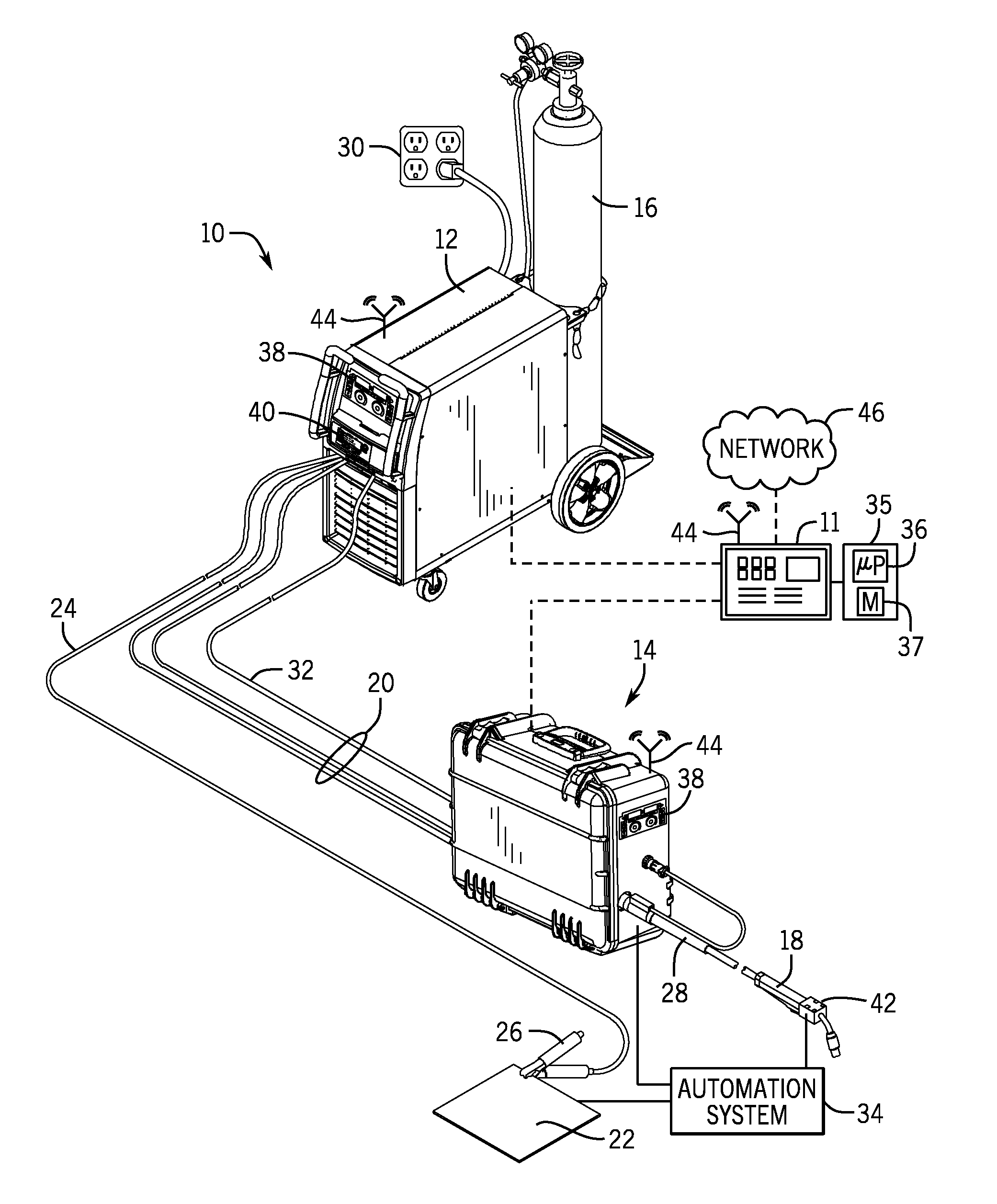
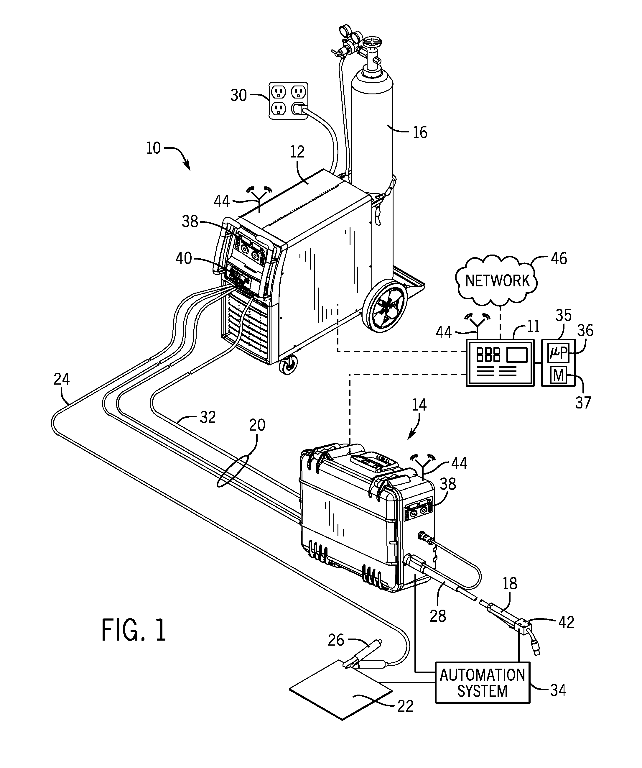
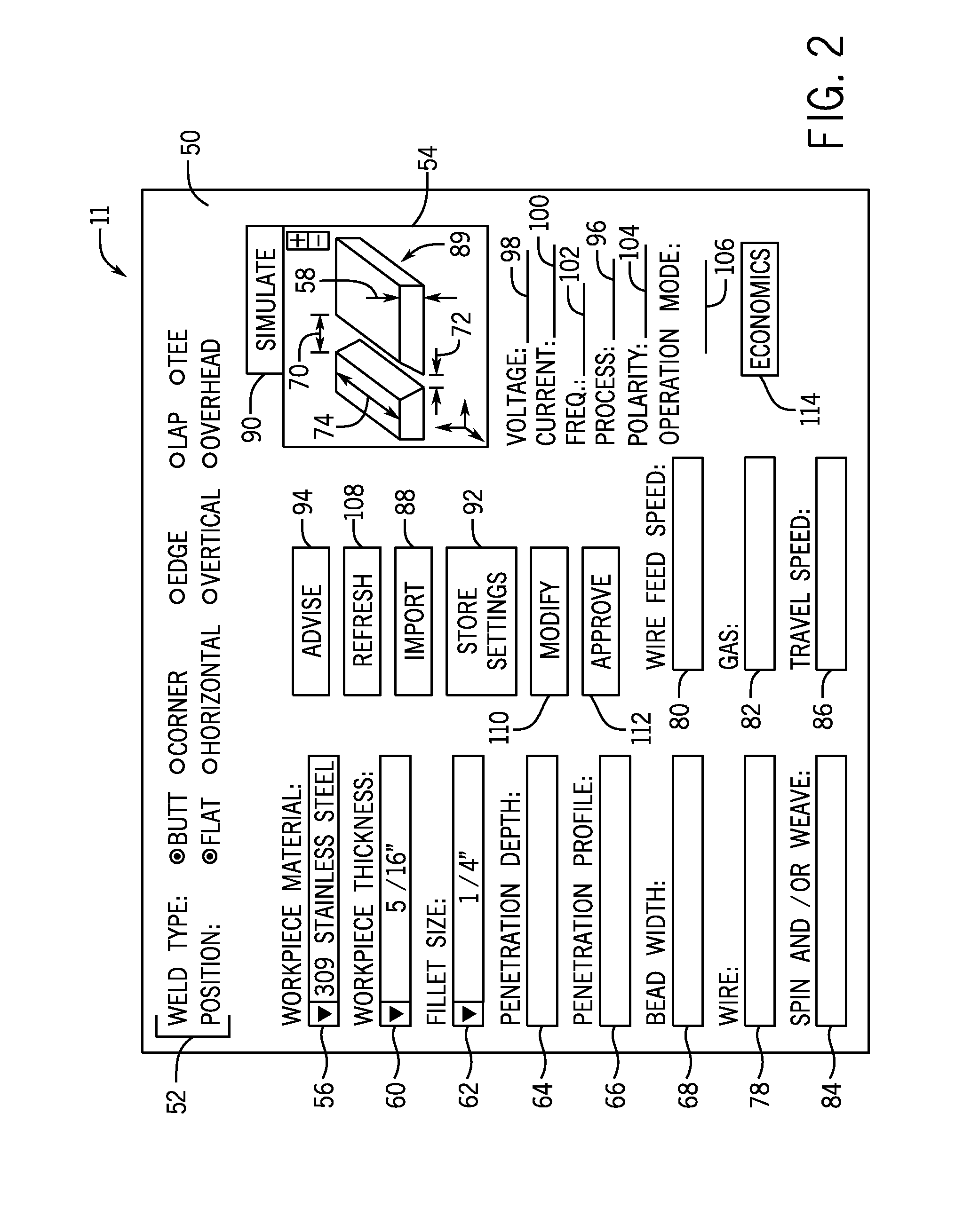
[0005]The welder interface described may increase synergy with the welding system for the user. The welder interface receives input parameters (e.g., physical characteristics) of a desired weld from a user and advises a weld process and weld variables (e.g., electrical parameters) for producing the desired weld. The welder interface may be integral with a component (e.g., power source, wire feeder, torch) of the welding system, or a separate component that may be coupled (e.g., wired or wireless connection) with the welding system. The welder interface may utilize data from a look-up table, neural network, welding procedure system, database, or any combination thereof to advise the weld process and weld variables. The user may utilize the welder interface to simulate the weld process and the effect of the weld variables on a simulated weld. The user may modify the input parameters and / or the weld variables prior to producing a weld, and the user may modify the weld variables after reviewing the results of the produced weld to refine the advised weld process and weld variables for subsequent welding applications.

Problems solved by technology

However, further divisions between these are common, particularly in processes that consume an electrode to add filler metal to the weld.
For example, solid wire, while less expensive than the other types, is typically used with inert shielding gases, which can be relatively expensive.
Flux cored wires may not require separate shielding gas feeds, but are more expensive than solid wires.
Unfortunately, user selection of the welding process and the weld settings for a particular application may be complex.

Method used


Image

  • System and method for selecting weld parameters
  • System and method for selecting weld parameters
  • System and method for selecting weld parameters

Examples


Embodiment Construction

[0011]One or more specific embodiments of the present invention will be described below. In an effort to provide a concise description of these embodiments, all features of an actual implementation may not be described in the specification. It should be appreciated that in the development of any such actual implementation, as in any engineering or design project, numerous implementation-specific decisions must be made to achieve the developers' specific goals, such as compliance with system-related and business-related constraints, which may vary from one implementation to another. Moreover, it should be appreciated that such a development effort might be complex and time consuming, but would nevertheless be a routine undertaking of design, fabrication, and manufacture for those of ordinary skill having the benefit of this disclosure.

[0012]When introducing elements of various embodiments of the present invention, the articles “a,”“an,”“the,” and “said” are intended to mean that ther...


PUM

PropertyMeasurementUnit
thicknessaaaaaaaaaa
frequencyaaaaaaaaaa
electrical parametersaaaaaaaaaa

Abstract

The welder interface described above may increase synergy with the welding system for the user. The welder interface receives input parameters of a desired weld from a user and advises a weld process and weld variables for producing the desired weld. The welder interface may be integral with a component of the welding system, or a separate component that may be coupled with the welding system. The welder interface may utilize data from a look-up table, neural network, welding procedure system, or database to advise the weld process and weld variables. The user may utilize the welder interface to simulate the weld process and the effect of the weld variables on a simulated weld. The user may modify the input parameters prior to producing a weld, and the user may modify the weld variables after reviewing the results of the produced weld for subsequent welding applications.

Description

CROSS-REFERENCE TO RELATED APPLICATIONS[0001]This application claims priority from and the benefit of U.S. Provisional Application Ser. No. 61 / 899,695, entitled “SYSTEM AND METHOD FOR SELECTING WELD PARAMETERS,” filed Nov. 4, 2013, and U.S. Provisional Application Ser. No. 61 / 900,198, entitled “SYSTEM AND METHOD FOR SELECTING WELD PARAMETERS,” filed Nov. 5, 2013, both of which are hereby incorporated by reference in their entireties for all purposes.BACKGROUND[0002]The invention relates generally to welding systems, and more particularly, to a system for selecting parameters for a welding system.[0003]A range of techniques have been developed for joining workpieces by welding operations. These include diverse processes and materials, with most modern processes involving arcs developed between a consumable or non-consumable electrode and the workpieces. Welding processes with non-consumable electrodes may include tungsten inert gas (TIG) welding processes, which employ a non-consumab...

Claims


Application Information

Patent Timeline
Patent Type & Authority Applications(United States)
IPC IPC(8): B23K9/10B23K9/095
CPCB23K9/10B23K9/0956B23K9/0953G05B19/0426G05B2219/45135
Inventor ALBRECHT, BRUCE PATRICK
Owner ILLINOIS TOOL WORKS INC
Why Eureka
Try Eureka