Device or method for displaying image

a display device and image technology, applied in image enhancement, color signal processing circuits, instruments, etc., can solve problems such as degrading image quality, and achieve the effect of increasing the amplitude of reflectan

Inactive Publication Date: 2015-05-07
EIZO
View PDF7 Cites 23 Cited by
  • Summary
  • Abstract
  • Description
  • Claims
  • Application Information

AI Technical Summary

Benefits of technology

[0006]The present invention has been made to solve the above problem, and an object thereof is to provide an image display device or image display method which can prevent degradation of image quality caused by excessive correction while improving the visibility of the dark portion, as well as can automatically adjust gradation conversion strength.Means For Solving The Problems
[0033]Thus, when the average is high, the content of the low-gradation component-enhanced illumination light component can be reduced, and / or it is possible to prevent an image which is distributed intensively at a high gradation from becoming difficult to see when the gradation of the image is corrected.

Problems solved by technology

Accordingly, use of the technique described above disadvantageously causes excessive correction, thereby degrading image quality.

Method used


Image

  • Device or method for displaying image
  • Device or method for displaying image
  • Device or method for displaying image

Examples


Embodiment Construction

[0045]An embodiment of the present invention will be described with reference to the drawings.

1. Outline

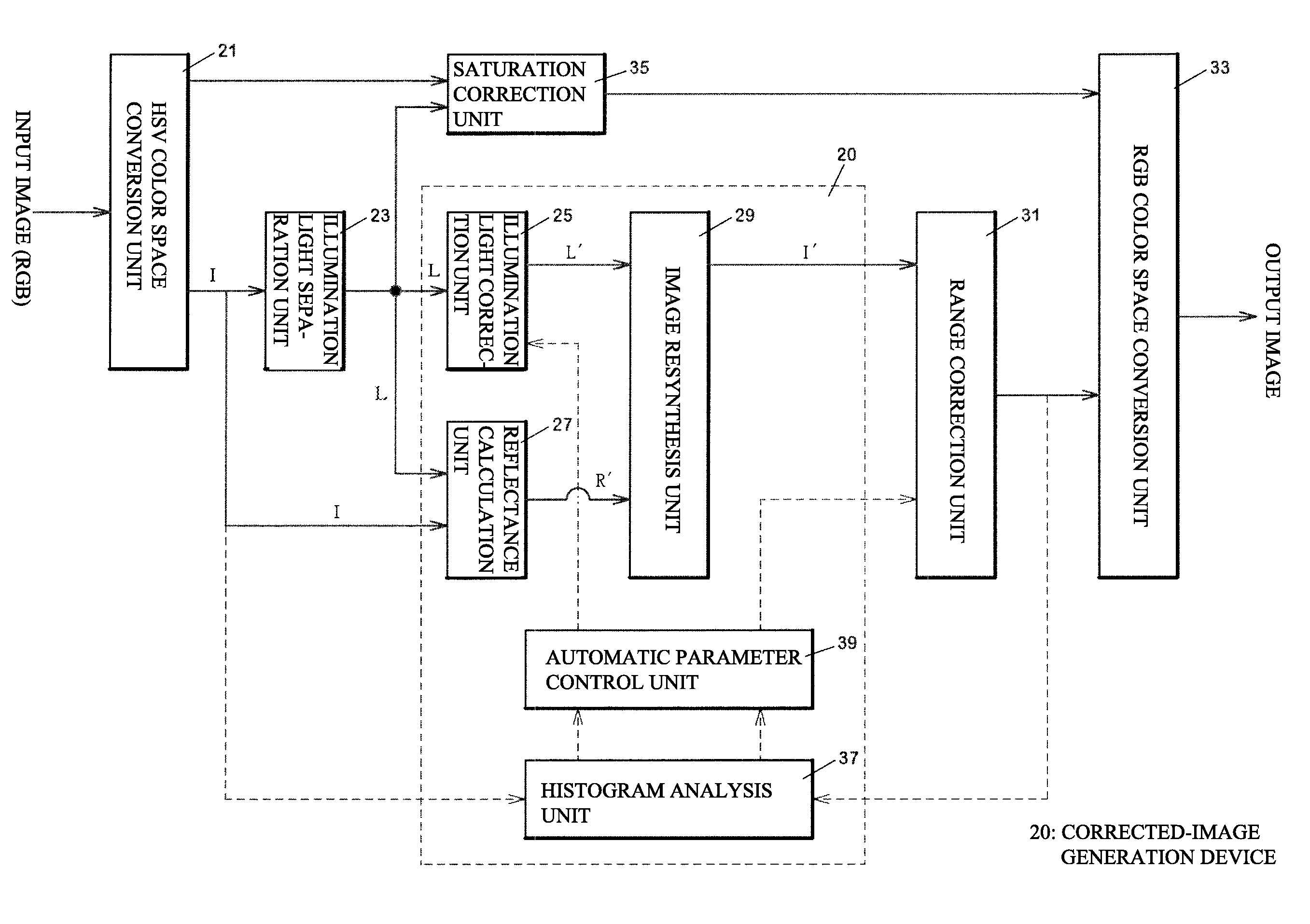
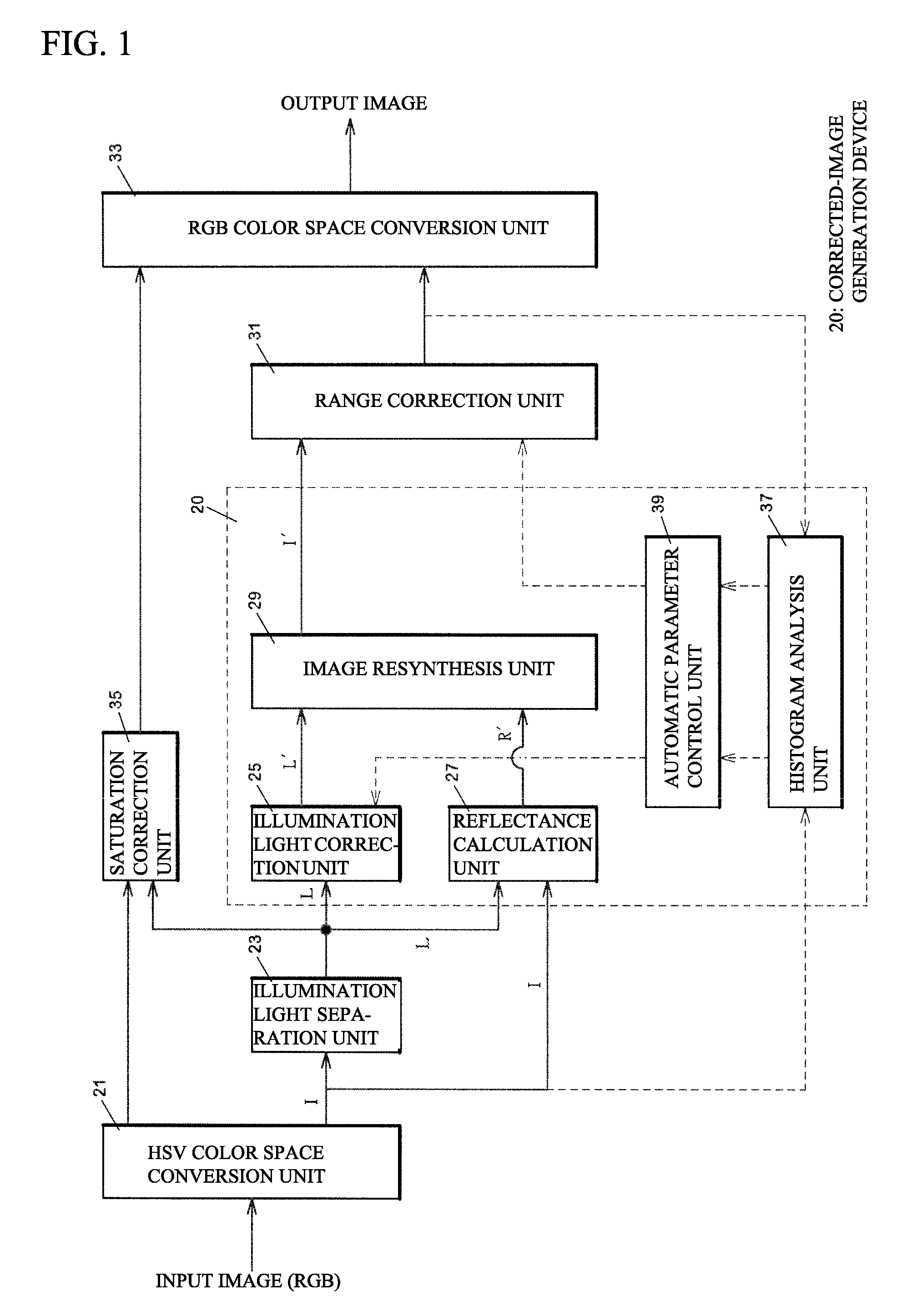
[0046]FIG. 1 shows a schematic diagram of an image display device including a corrected-image generation device 20 according to the present embodiment. In the present embodiment, an illumination light correction unit 25, a reflectance calculation unit 27, an image resynthesis unit 29, an automatic parameter control unit 39, a histogram analysis unit 37 form a gradation correction device.

[0047]An HSV color space conversion unit 21 converts RGB color space into HSV color space. The HSV color space is converted into the RGB color space using a typical conversion formula. Use of HSV color space allows elimination of saturation reduction effects resulting from the adjustment of brightness using YUV color space and thus visually favorable correction of brightness.

[0048]An illumination light separation unit 23 is an edge-preserving low-pass filter and calculates the weighted average of l...


PUM


Abstract

Improving the visibility of the dark portion and to prevent the degradation of image quality caused by excessive correction. A reflectance calculation unit is storing a parameter RGain for adjusting the amplitude of a reflectance component R. An illumination light correction unit generates a corrected illumination light component L1 from an illumination light component L and a formula L1=(log(LAmp*L+1)) / (log(LAmp+1)). An image resynthesis unit obtains a corrected illumination light component L′ from L′=LGain*L1 +(1−LGain)*L. The image resynthesis unit also calculates a corrected image Tout from the corrected illumination light component L′ and the corrected reflectance R′, as well as from a formula Iout=exp(log L′+RGain(log I−log L)). The value of the corrected illumination light component (L′) is determined based on the ratio (LGain) at which the output value of the correction function (L1) and the original illumination light component (L) are combined.

Description

TECHNICAL FIELD[0001]The present invention relates to Retinex processing in an image display device and in particular to adjustment of gradation conversion strength.BACKGROUND ART[0002]Image processing based on the Retinex theory is known as a method for compressing the dynamic range of an imaging device. Since the dynamic range of an imaging device is smaller than the dynamic range of the natural world, the dynamic range is compressed by separating, compressing, and resynthesizing an illumination light component on the basis of the Retinex theory.[0003]Single-scale Retinex (SSR) is known as a type of image processing based on the Retinex theory. In the Retinex theory, incident light I is defined as the product of illumination light L and reflectance R (I=RL). Based on this formula, logR in logarithmic space is used as the output value of the image (see paragraph 0007 of Patent Document 1).logR=logI−logLThe above formula shows that, assuming that corrected illumination light L′ is a...

Claims


Application Information

Patent Timeline
Patent Type & Authority Applications(United States)
IPC IPC(8): G06T5/00G06T5/20G09G5/02
CPCG06T5/009G09G5/02G09G2320/0673G06T2207/20208G09G2320/066G06T5/20H04N5/66G06T5/008H04N9/68G09G5/20G09G2320/0626
Inventor ABE, REONAKAO, MASASHIHIGASHI, MASAFUMI
Owner EIZO
Why Eureka
Try Eureka