Backlight unit for display devices

Active Publication Date: 2015-05-07
NANOSYS INC
View PDF7 Cites 44 Cited by
  • Summary
  • Abstract
  • Description
  • Claims
  • Application Information

AI Technical Summary

Benefits of technology

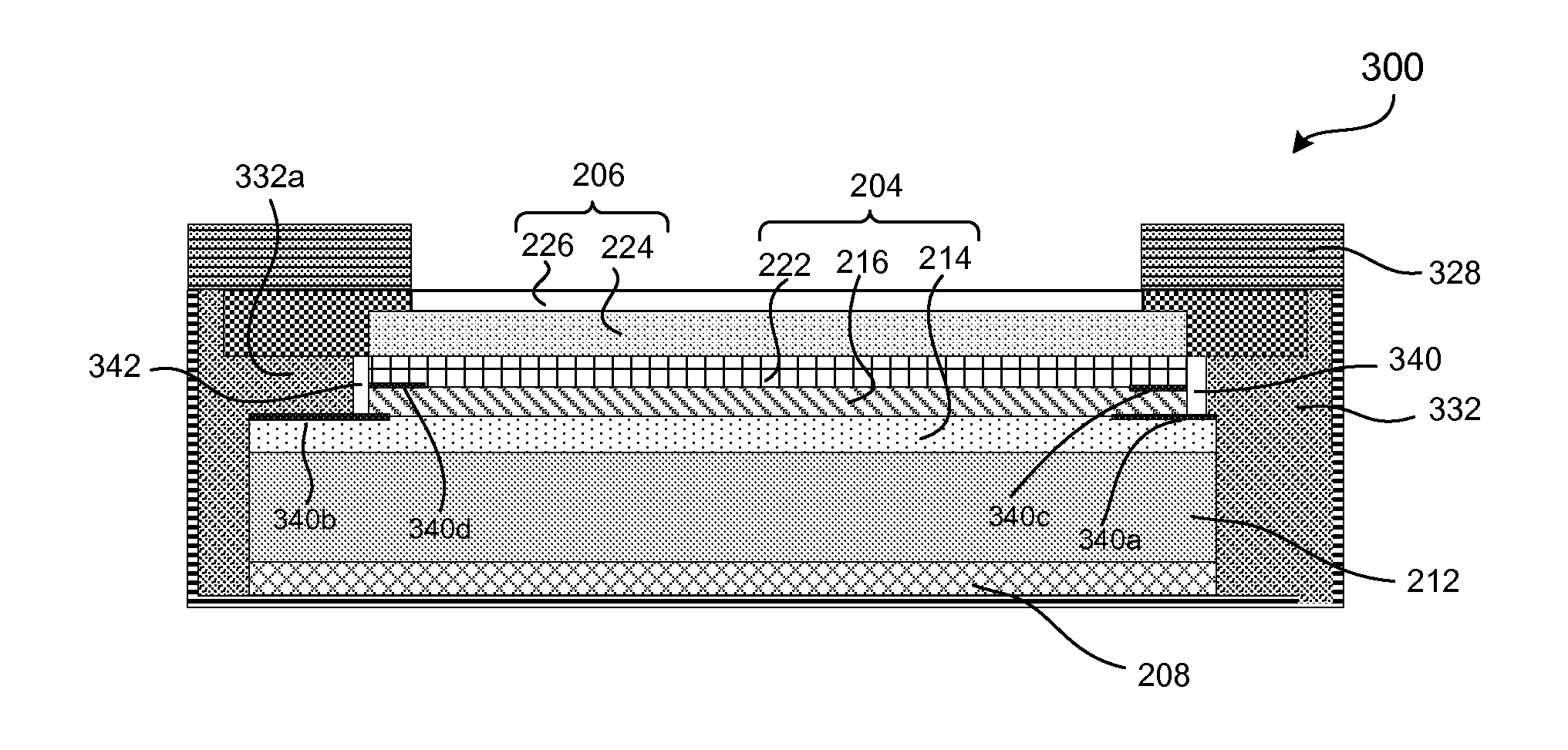
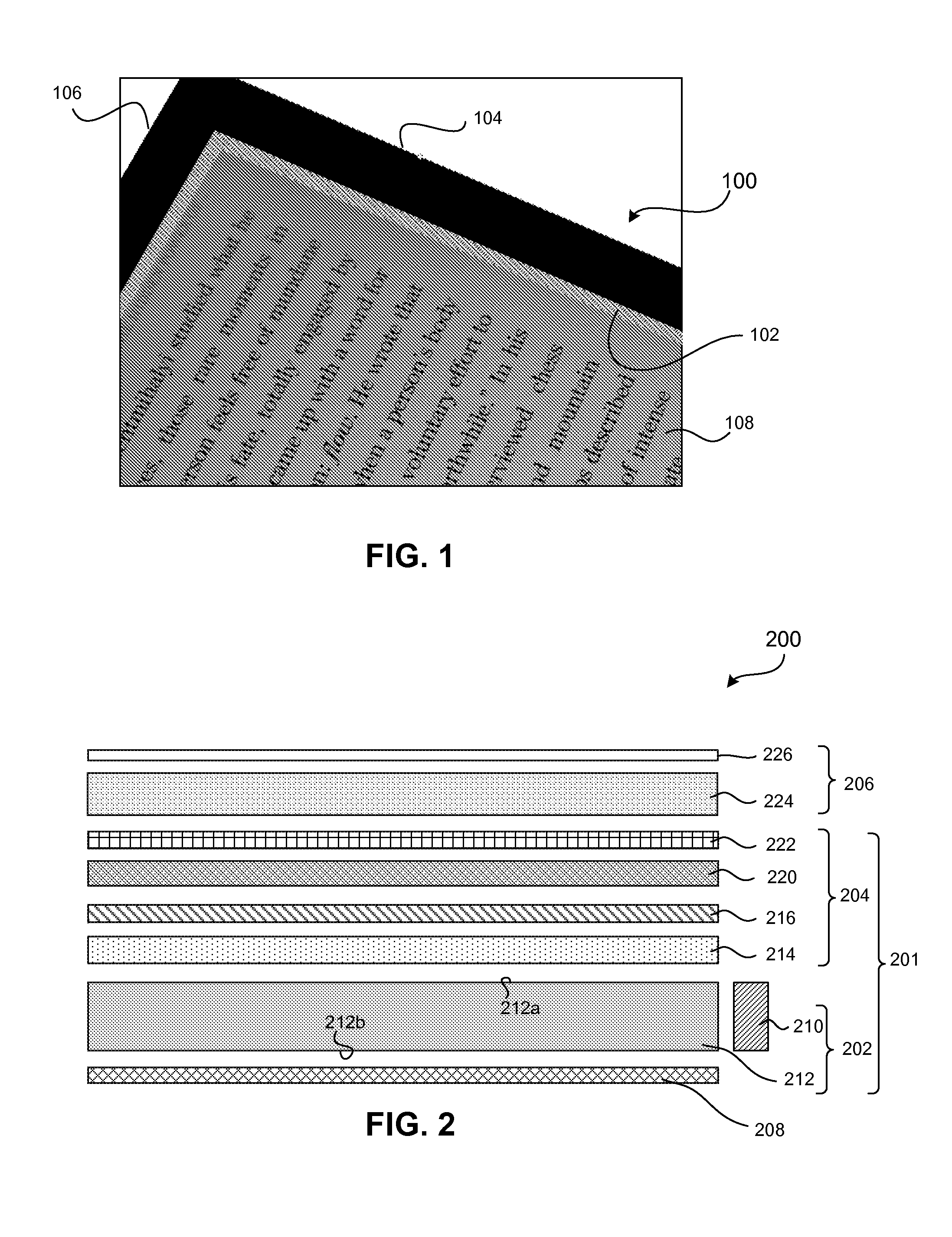
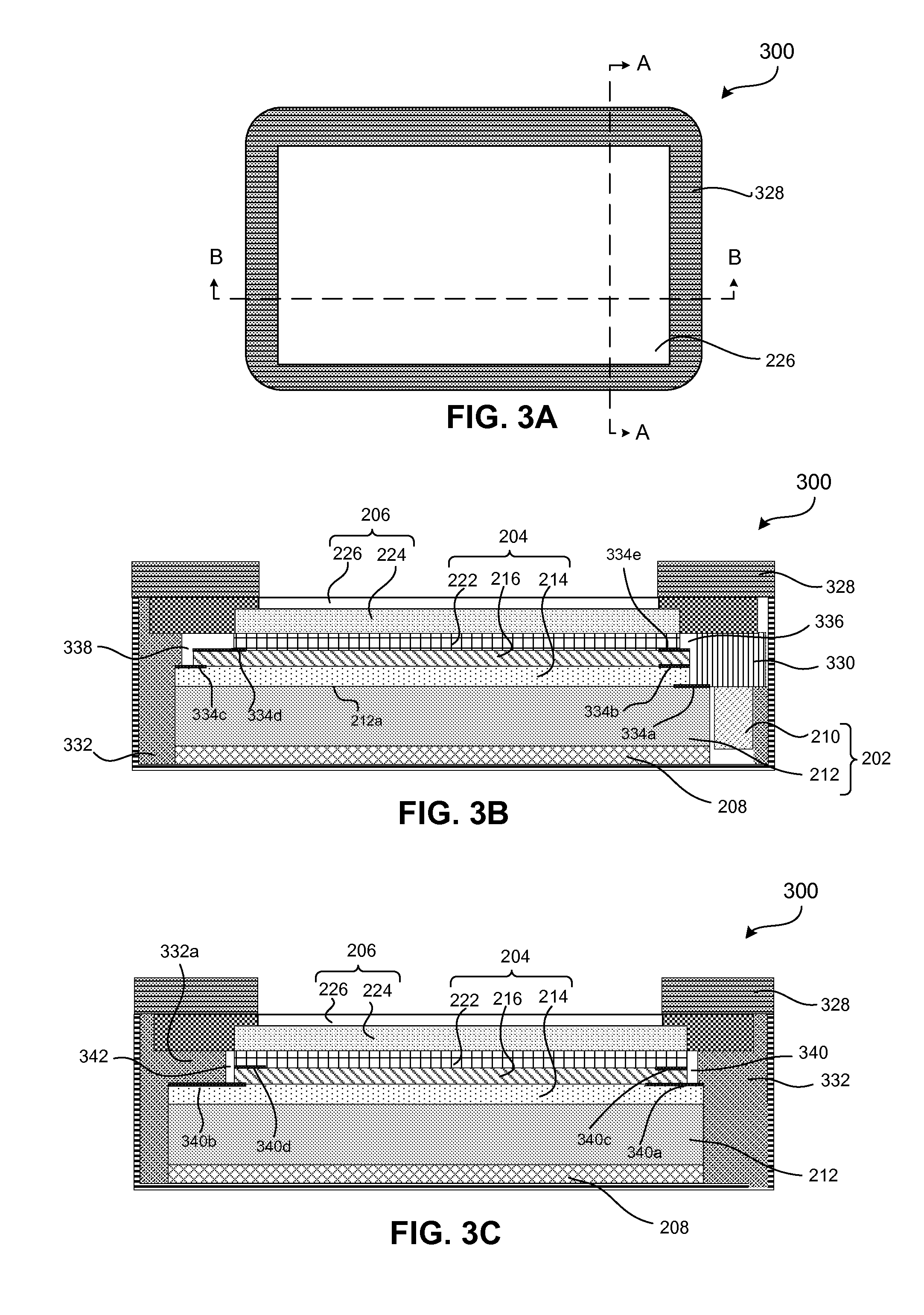
[0027]According to another embodiment, a method of reducing optical leakage from a backlight unit of a display device includes providing a light source unit, providing an optical processing unit, providing a

Problems solved by technology

This hue of light may be a problem when color

Method used


Image

  • Backlight unit for display devices
  • Backlight unit for display devices
  • Backlight unit for display devices

Examples


Embodiment Construction

[0039]Although specific configurations and arrangements may be discussed, it should be understood that this is done for illustrative purposes only. A person skilled in the pertinent art will recognize that other configurations and arrangements can be used without departing from the spirit and scope of the present invention. It will be apparent to a person skilled in the pertinent art that this invention can also be employed in a variety of other applications beyond those specifically mentioned herein. It should be appreciated that the particular implementations shown and described herein are examples and are not intended to otherwise limit the scope of the application in any way.

[0040]It is noted that references in the specification to “one embodiment,”“an embodiment,”“an example embodiment,” etc., indicate that the embodiment described may include a particular feature, structure, or characteristic, but every embodiment may not necessarily include the particular feature, structure, ...


PUM


Abstract

Embodiments of a display device and a method of reducing optical leakage from a backlight unit of a display device are described. The display device includes a backlight unit, an image generating unit coupled to the backlight unit and a blocking structure. The backlight unit is configured to transit light to the image generating unit and the blocking structure is configured to prevent the light from reaching the image generating unit without passing through the optical processing unit. The backlight unit includes a light source unit and an optical processing unit having a quantum dot film coupled to the light source unit. The method of reducing optical leakage from the backlight unit of the display device includes providing a first blocking structure to a portion of the light source unit and providing a second blocking structure to a portion of the optical processing unit.

Description

BACKGROUND OF THE INVENTION[0001]1. Field[0002]The present invention relates to display devices comprising light-emitting diodes (LEDs) and films including luminescent nanocrystals such as quantum dots (QDs).[0003]2. Background[0004]In a backlight unit (BLU) of a display device (e.g., liquid crystal displays (LCDs)), LEDs are typically utilized as a light source. The LEDs may be arranged around the edge or perimeter of the display device and light emanating from the LEDs may enter a light guide plate (LGP), which distributes white light uniformly across the display device. White LED package designs have been optimized to enable high extraction efficiency and coupling efficiency into the LGP.[0005]The BLUs often utilize phosphors, such as yttrium-aluminum-garnet (YAG) phosphors inside the LED package itself. Luminescent nanocrystals represent a new, alternative class of phosphors often used in configurations where the phosphor is placed external to the LED package. For example, lumin...

Claims


Application Information

Patent Timeline
IPC IPC(8): G02F1/01F21V9/14F21V8/00
CPCG02F1/0105F21V9/14G02B6/0073G02B6/0023G02B6/005G02B6/0065G02F1/133512G02F1/133603G02F1/133615G02F1/133388G02F1/133614G02F1/133611
Inventor CHEN, JIANGENSLER, STEVEN
Owner NANOSYS INC
Why Eureka
Try Eureka