Zoom lens system

a zoom lens and lens group technology, applied in the field of zoom lens system, can solve the problems of enlargement of the entire zoom lens system, insufficient optical quality, and increased burden on the drive mechanism of the image stabilizing lens group, so as to reduce the burden on the drive mechanism, improve the optical quality, and facilitate aberration correction

Inactive Publication Date: 2015-05-07
RICOH IMAGING COMPANY
View PDF1 Cites 14 Cited by
  • Summary
  • Abstract
  • Description
  • Claims
  • Application Information

AI Technical Summary

Benefits of technology

[0023]The present invention has been devised in view of the above-mentioned problems, and provides a zoom lens system which, in particular, achieves a superior optical quality by favorably correcting aberrations which occur during an image-stabilizing drive operation (when decentering the image-stabilizing lens group), while reducing the burden on the drive mechanism of the image-stabilizing lens group, miniaturizing the entire zoom lens system (and also the entire apparatus including the image-stabilizing lens group), and reducing the manufacturing cost.
[0024]Furthermore, in a wide-angle zoom lens system for use in a single-reflex camera in particular, the present invention also obtains a high optical quality over the entire focal length range and over the entire photographing distance range while suppressing abaxial aberrations such as distortion, field curvature, astigmatism, and lateral chromatic aberration, etc.
[0046]According to the present invention, a zoom lens system is provided which, in particular, achieves a superior optical quality by favorably correcting aberrations which occur during an image-stabilizing drive operation (when decentering the image-stabilizing lens group), while reducing the burden on the drive mechanism of the image-stabilizing lens group, miniaturizing the entire zoom lens system (and also the entire apparatus including the image-stabilizing lens group), and reducing the manufacturing cost.
[0047]Furthermore, according to the present invention, in a wide-angle zoom lens system for use in a single-reflex camera in particular, a high optical quality is achieved over the entire focal length range and over the entire photographing distance range while suppressing abaxial aberrations such as distortion, field curvature, astigmatism, and lateral chromatic aberration, etc.

Problems solved by technology

In regard to such requirements, in order to apply the image-stabilizing zoom lens systems disclosed in Patent Literature 1 through 4 to a highly-pixelized digital camera, etc., which requires a relatively high optical quality, the correction of aberrations during an image-stabilizing drive operation (during decentering of an image-stabilizing lens group) and the optical quality are insufficient.
However, if the number of lens elements of the image-stabilizing lens group are increased too much, the burden on the drive mechanism for the image-stabilizing lens group increases, and also causes enlargement of the entire zoom lens system (and also the entire apparatus which includes the drive mechanism of the image-stabilizing lens group).
Furthermore, an increase in the number of lens elements in the image-stabilizing lens group and the use of lens elements having at least one aspherical surface become a cause for increasing the manufacturing costs.
Generally, in a wide-angle zoom lens system, since abaxial aberrations such as distortion, field curvature, astigmatism, and lateral chromatic aberration, etc., occur together with a zooming operation or a focusing operation being carried out, it is difficult to obtain a high optical quality over the entire focal length range and over the entire photographing distance range.

Method used


Image

  • Zoom lens system
  • Zoom lens system
  • Zoom lens system

Examples


numerical embodiment 1

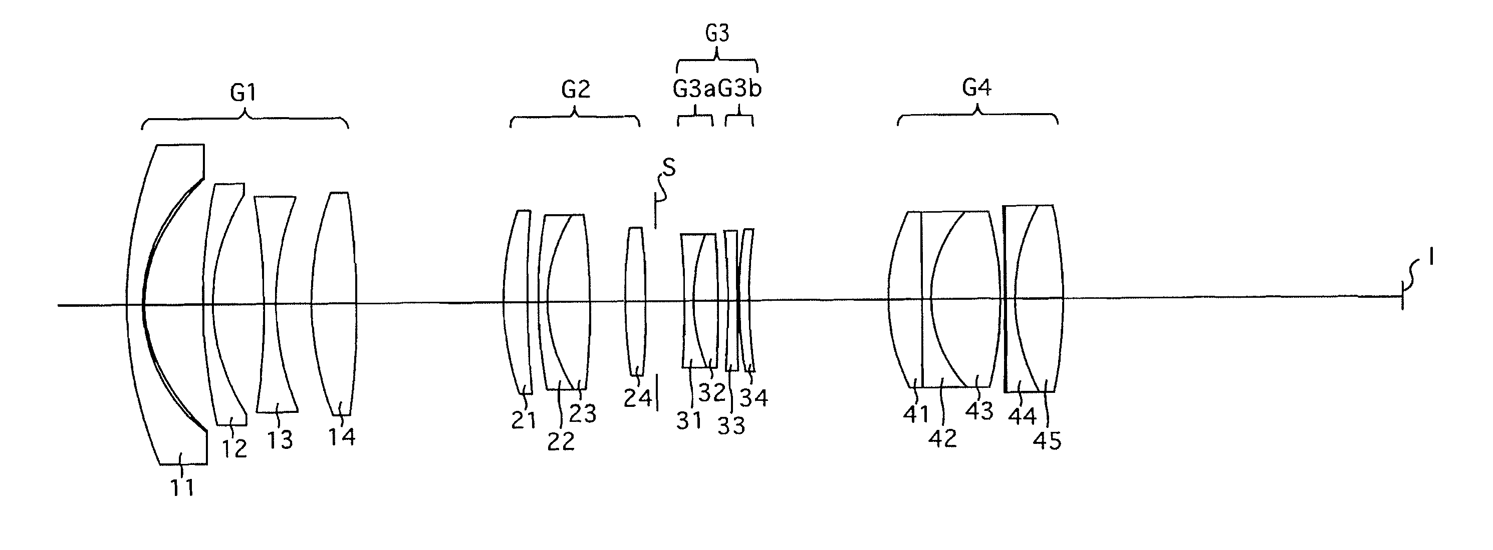
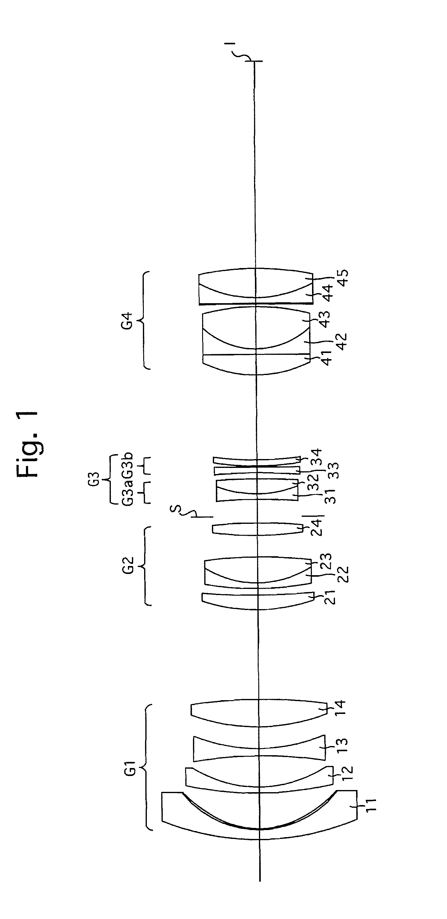
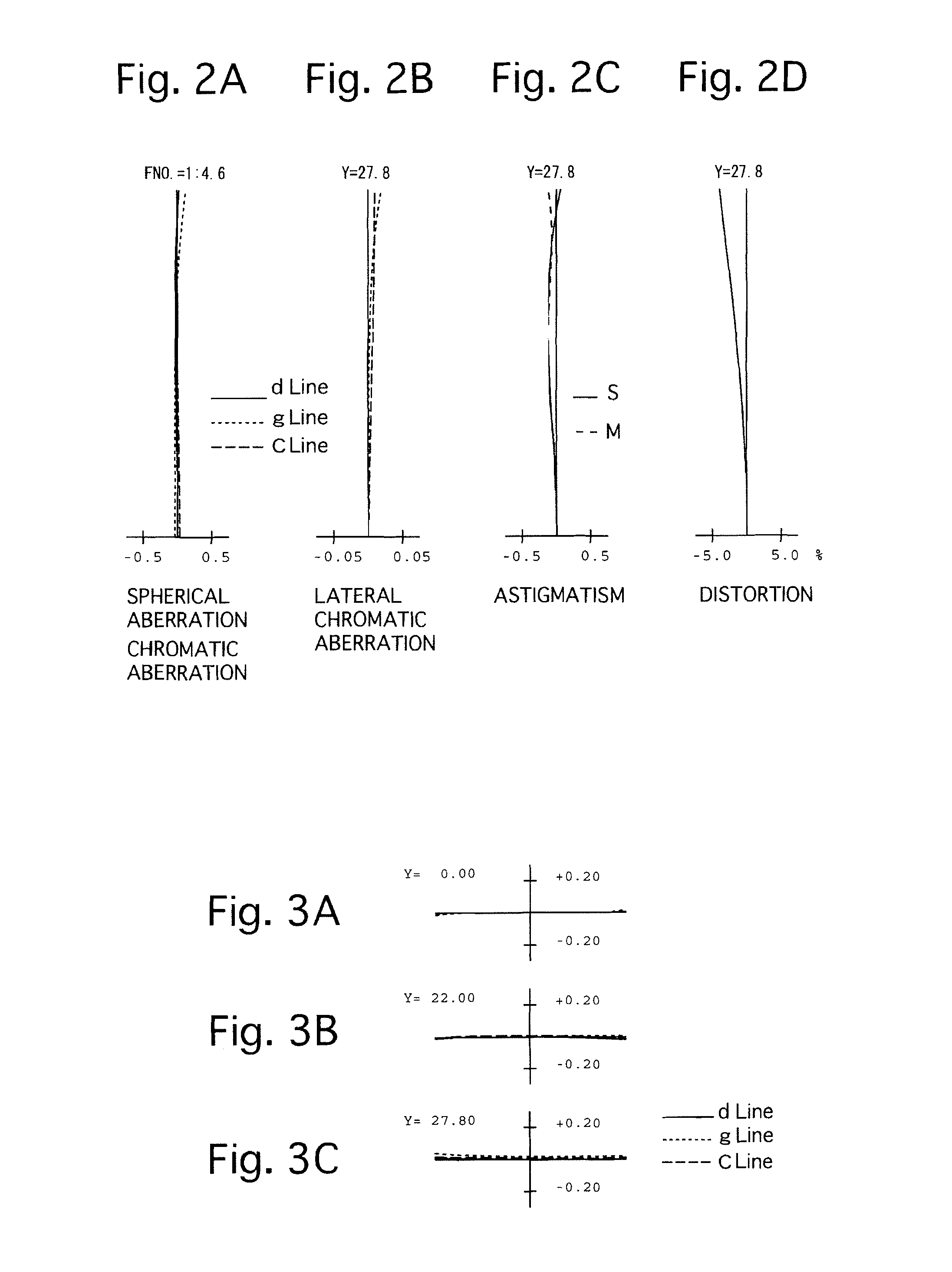
[0266]FIGS. 1 through 10C and Tables 1 through 5 show a first numerical embodiment of the zoom lens system according to the present invention. FIG. 1 shows a lens arrangement of the first numerical embodiment of the zoom lens system, at the short focal length extremity when focused on an object at infinity. FIGS. 2A, 2B, 2C and 2D show various aberrations that occurred in the lens arrangement shown in FIG. 1, at the short focal length extremity when focused on an object at infinity. FIGS. 3A, 3B and 3C show lateral aberrations that occurred in the lens arrangement shown in FIG. 1, at the short focal length extremity when focused on an object at infinity. FIGS. 4A, 4B, 4C and 4D show various aberrations that occurred in the lens arrangement shown in FIG. 1, at an intermediate focal length when focused on an object at infinity. FIGS. 5A, 5B and 5C show lateral aberrations that occurred in the lens arrangement shown in FIG. 1, at an intermediate focal length when focused on an object a...

numerical embodiment 2

[0275]FIGS. 11 through 20C and Tables 6 through 10 show a second numerical embodiment of the zoom lens system according to the present invention. FIG. 11 shows a lens arrangement of the second numerical embodiment of the zoom lens system, at the short focal length extremity when focused on an object at infinity. FIGS. 12A, 12B, 12C and 12D show various aberrations that occurred in the lens arrangement shown in FIG. 11, at the short focal length extremity when focused on an object at infinity. FIGS. 13A, 13B and 13C show lateral aberrations that occurred in the lens arrangement shown in FIG. 11, at the short focal length extremity when focused on an object at infinity. FIGS. 14A, 14B, 14C and 14D show various aberrations that occurred in the lens arrangement shown in FIG. 11, at an intermediate focal length when focused on an object at infinity. FIGS. 15A, 15B and 15C show lateral aberrations that occurred in the lens arrangement shown in FIG. 11, at an intermediate focal length when...

numerical embodiment 3

[0277]FIGS. 21 through 30C and Tables 11 through 15 show a third numerical embodiment of the zoom lens system according to the present invention. FIG. 21 shows a lens arrangement of the third numerical embodiment of the zoom lens system, at the short focal length extremity when focused on an object at infinity. FIGS. 22A, 22B, 22C and 22D show various aberrations that occurred in the lens arrangement shown in FIG. 21, at the short focal length extremity when focused on an object at infinity. FIGS. 23A, 23B and 23C show lateral aberrations that occurred in the lens arrangement shown in FIG. 21, at the short focal length extremity when focused on an object at infinity. FIGS. 24A, 24B, 24C and 24D show various aberrations that occurred in the lens arrangement shown in FIG. 21, at an intermediate focal length when focused on an object at infinity. FIGS. 25A, 25B and 25C show lateral aberrations that occurred in the lens arrangement shown in FIG. 21, at an intermediate focal length when ...


PUM


Abstract

A zoom lens system includes a negative first lens group, a positive second lens group, a negative third lens group and a positive fourth lens group, in that order from the object side. Upon zooming from the short to long focal length extremities, at least the first lens group, the second lens group and the fourth lens group are moved in the optical axis direction. The third lens group includes a negative first sub-lens group and a negative second sub-lens group, in that order from the object side. The second sub-lens group is provided with a negative single lens element and a positive single lens element, wherein an air lens is formed between the negative single lens element and the positive single lens element.

Description

BACKGROUND OF THE INVENTION[0001]1. Field of the Invention[0002]The present invention relates to a zoom lens system, and in particular, relates to a wide-angle zoom lens system that is favorable for use in a single-lens reflex camera. In addition, the present invention relates to an intra-lens image-stabilizing zoom optical system in which part of the lens system thereof can be decentered in order to correct image-blur caused by vibrations / hand-shake, etc.[0003]2. Description of Related Art[0004]Since it is relatively easy for a so-called “negative-lead zoom lens system”, in which a lens group having a negative refractive power is provided closest to the object side, to obtain a wide angle-of-view and a long backfocus relative to the focal length, negative-lead zoom lens systems are often utilized in wide-angle zoom lens systems for use in a single-lens reflex camera.[0005]A number of negative-lead zoom lens systems have been proposed in which an image-stabilizing function (image-sh...

Claims


Application Information

Patent Timeline
Patent Type & Authority Applications(United States)
IPC IPC(8): G02B15/177G02B13/00G02B27/64
CPCG02B15/177G02B13/009G02B27/646G02B15/16G02B15/20G02B15/144511G02B15/14G02B15/163G02B15/167G03B2205/0046
Inventor ONOZAKI, TATSUYUKI
Owner RICOH IMAGING COMPANY
Why Eureka
Try Eureka