Power conversion system

Active Publication Date: 2015-05-07
SAAB AB
4 Cites 5 Cited by

AI-Extracted Technical Summary

Problems solved by technology

Such a system is sensitive to failures in the power conversion unit.
A drawback with such a solutions could be that both power conversion units 101, 102 suffers the same number of start and stops as the load 120, and each also logs the sam...

Benefits of technology

[0007]Since the power up operation and to a certain degree also the power down operation are critical operations regarding the electronics because, this is the moments at which electronic components break. An advantage with the solution according the invention is that the number of power ups is reduced to half for each power conversion unit and the probability for each converter failing will also be reduced to half. ...

Abstract

A power converter system suitable to provide a load with electrical power, the system comprising; an input voltage terminal; an output voltage terminal; a first power converter unit; a second power converter unit; an input relay unit; an output relay unit; a control unit; wherein the control unit is configured to control the input relay unit and the output relay unit such that the first and second power converter units are engaged alternating at subsequent power ups of the voltage input terminal.

Application Domain

Technology Topic

Image

  • Power conversion system
  • Power conversion system
  • Power conversion system

Examples

  • Experimental program(1)

Example

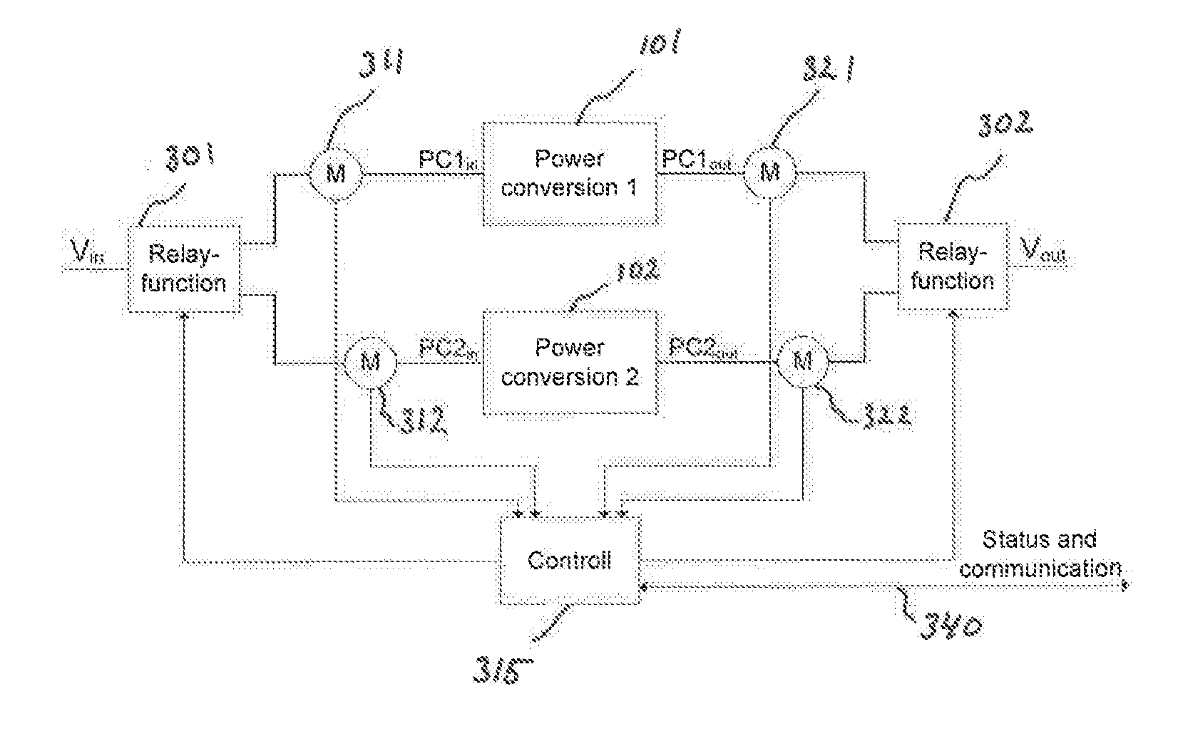
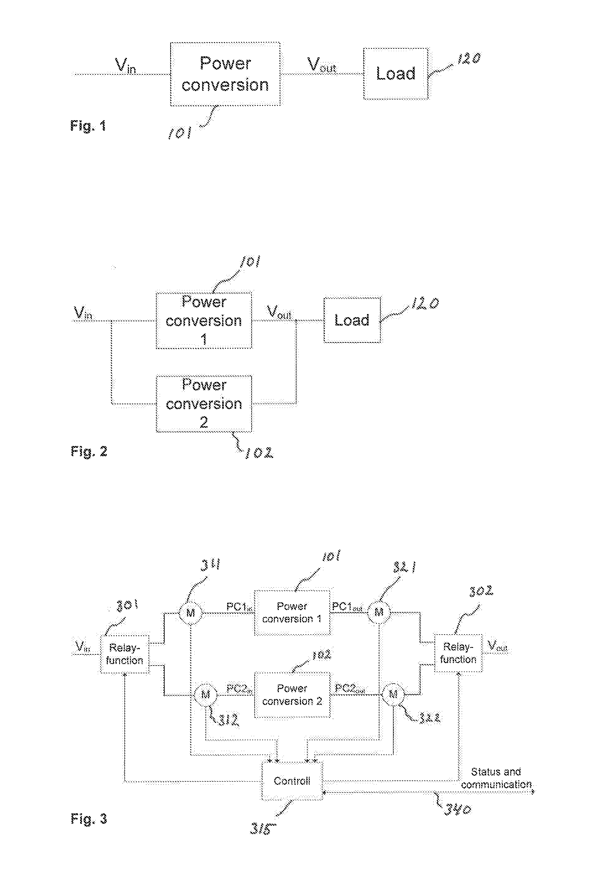
[0035]A solution to the above identified problems as devised by the inventors is to provide a relay arrangement 301, 302 comprising a first 301 and a second relay unit 302 to the power converter system of FIG. 2, resulting in the power converter system of FIG. 3. The relay units being provided with connections to a control unit 315, which control unit has been configured to control the relay units 301, 302 in order to engage the first power conversion unit 101 or the second power conversion unit 102 based on certain rules and/or inputs to the control unit 315. More about this will follow below.
[0036]The control unit 315 may preferably be configured to alternate start-ups between the two power converters. This could be predetermined to be every second time, every third time, every fourth time etc. The control unit may as an alternative be configured to randomly distribute the start-ups between the power converters, with a 50% probability over time for engaging each of them. This may be achieved by providing a random number generator and a rule by which a random number generated by the random number generator is converted to a power converter number. Alternate probabilities may be contemplated. The solution as described herein shall not be interpreted as confined to two converters also a solution with three or more converters may be contemplated to increase MTBF further. The probability figures for each converter being used then may be arranged to be 1/N, where N is the number of converters.
[0037]Measuring sensors M 311, 312, 321, 322, may be arranged to measure the voltage, and also possibly the current of the input and output of each converter, see FIG. 3, to be able to decide if any of the converter units are failing.
[0038]The control unit 315 is configured to disengage a broken, or breaking, converter. If any of the converters 101, 102 fail, the control unit 315 is configured to disengage that converter and let the fully functioning converter handle all start-ups. Preferably, the control unit is configured to issue an alarm signal, e.g. via a status and communication connection 340.
[0039]FIG. 3 thus shows a power supply system with two redundant power conversion units which is also provided with relays and control means to appropriately switch between them. The same principle rule also when more than two converter units are used. When a voltage is applied at input terminal Vin, the system powers up, i.e. starts.
[0040]FIG. 4a, 4b, 4c shows in total three detail examples of the relay unit of FIG. 3. In FIG. 4a an alternating relay is shown. In FIG. 4b is shown a solution where each connection can be individually controlled. FIG. 4c shows a relay wherein connection is alternating between two positions at start-up, but having a third state wherein both converters are disconnected.
How to Decide Active Converter Unit
[0041]Internally, the control unit 315 may be provided with a counter that keeps track of which converter to start up next time. Depending on the number of power converter units to be used, the counter provides information to alternate between them. When there are two converters this may be implemented by letting a binary digit change between 0 and 1, where the numbers refers to one specific converter of the two.
A Method
[0042]FIG. 5 shows a flow chart of a power converter control method for controlling two converters. The method controls which converter to engage in the power converter system described above, and in FIG. 3. The method may comprise the following steps. [0043] Deciding 510 if input voltage is applied [0044] Deciding 520 which power converter that are in turn to be activated/engaged [0045] Checking 531 if a first converter unit PC1 was OK last time, and if not checking if it is replaced 539, i.e., exchanged for a functioning substitute; [0046] Checking 541 further converters accordingly; [0047] Engaging 533, 543 an OK converter by setting the relay units properly; [0048] Checking 535, 545, continuously the output signal; If a converter unit is fed with input voltage but there is no corresponding output voltage, there is set a flag “PCx not OK”, and that converter will not pass the test for OK in step(s) 531, 541; [0049] Issuing 537, 547 an alarm if one of the converters are failing.

PUM

no PUM

Description & Claims & Application Information

We can also present the details of the Description, Claims and Application information to help users get a comprehensive understanding of the technical details of the patent, such as background art, summary of invention, brief description of drawings, description of embodiments, and other original content. On the other hand, users can also determine the specific scope of protection of the technology through the list of claims; as well as understand the changes in the life cycle of the technology with the presentation of the patent timeline. Login to view more.

Similar technology patents

Classification and recommendation of technical efficacy words

  • Reduce number
  • Increase probability

Seizure forecasting, microseizure precursor events, and related therapeutic methods and devices

InactiveUS20100292602A1Prevent seizureIncrease probabilityElectroencephalographyHead electrodesEpilepsyEpileptogenic zone
Owner:MAYO FOUND FOR MEDICAL EDUCATION & RES
Why Eureka
Try Eureka