X-ray tube rotor with carbon composite based material

Active Publication Date: 2015-05-07
KONINKLJIJKE PHILIPS NV
View PDF0 Cites 3 Cited by
  • Summary
  • Abstract
  • Description
  • Claims
  • Application Information

AI Technical Summary

Benefits of technology

[0003]Thus, there is a need to provide further possibilities for weight

Problems solved by technology

However, it has been shown that the thermal mechanical properties of

Method used


Image

  • X-ray tube rotor with carbon composite based material
  • X-ray tube rotor with carbon composite based material
  • X-ray tube rotor with carbon composite based material

Examples


Embodiment Construction

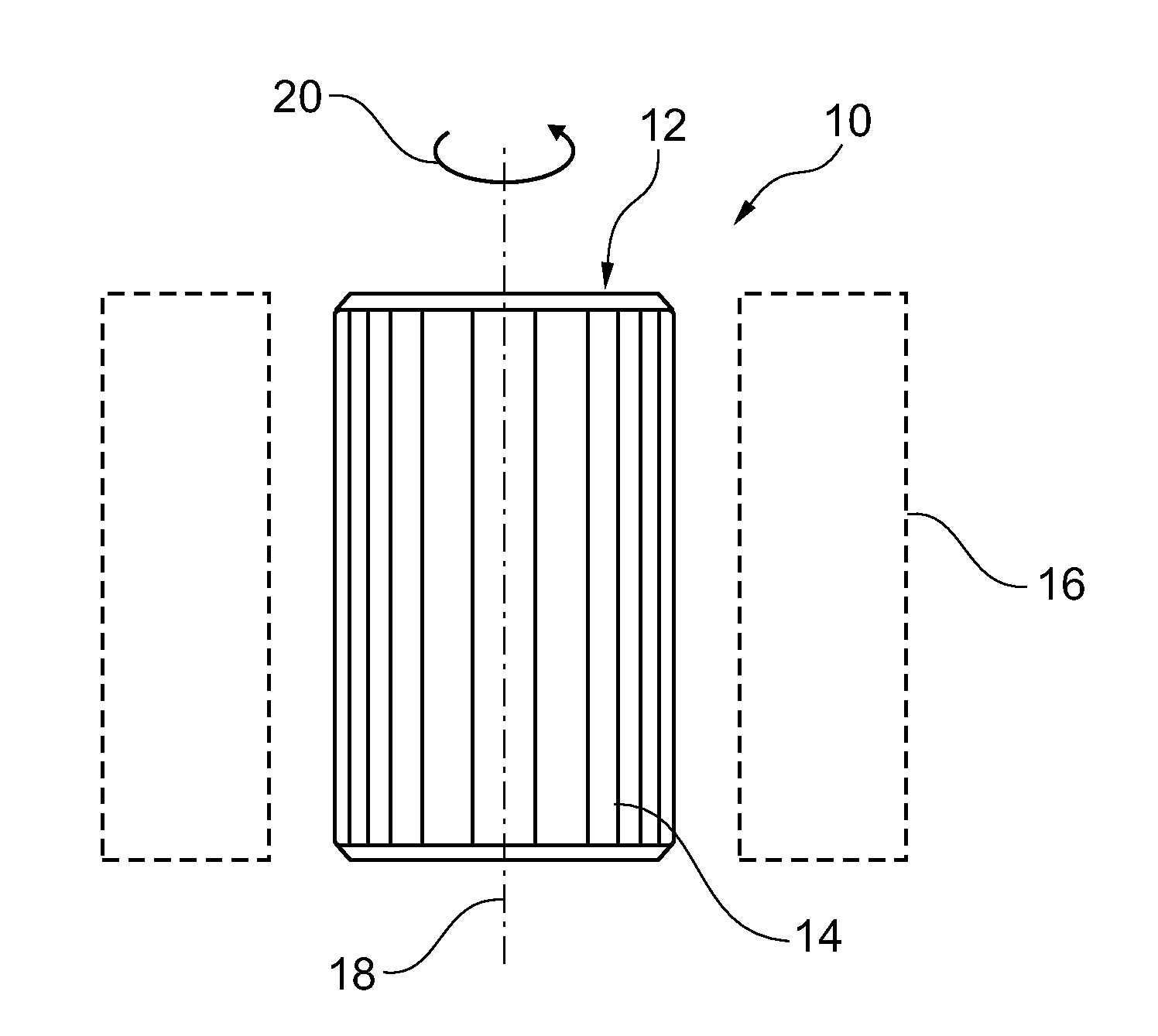
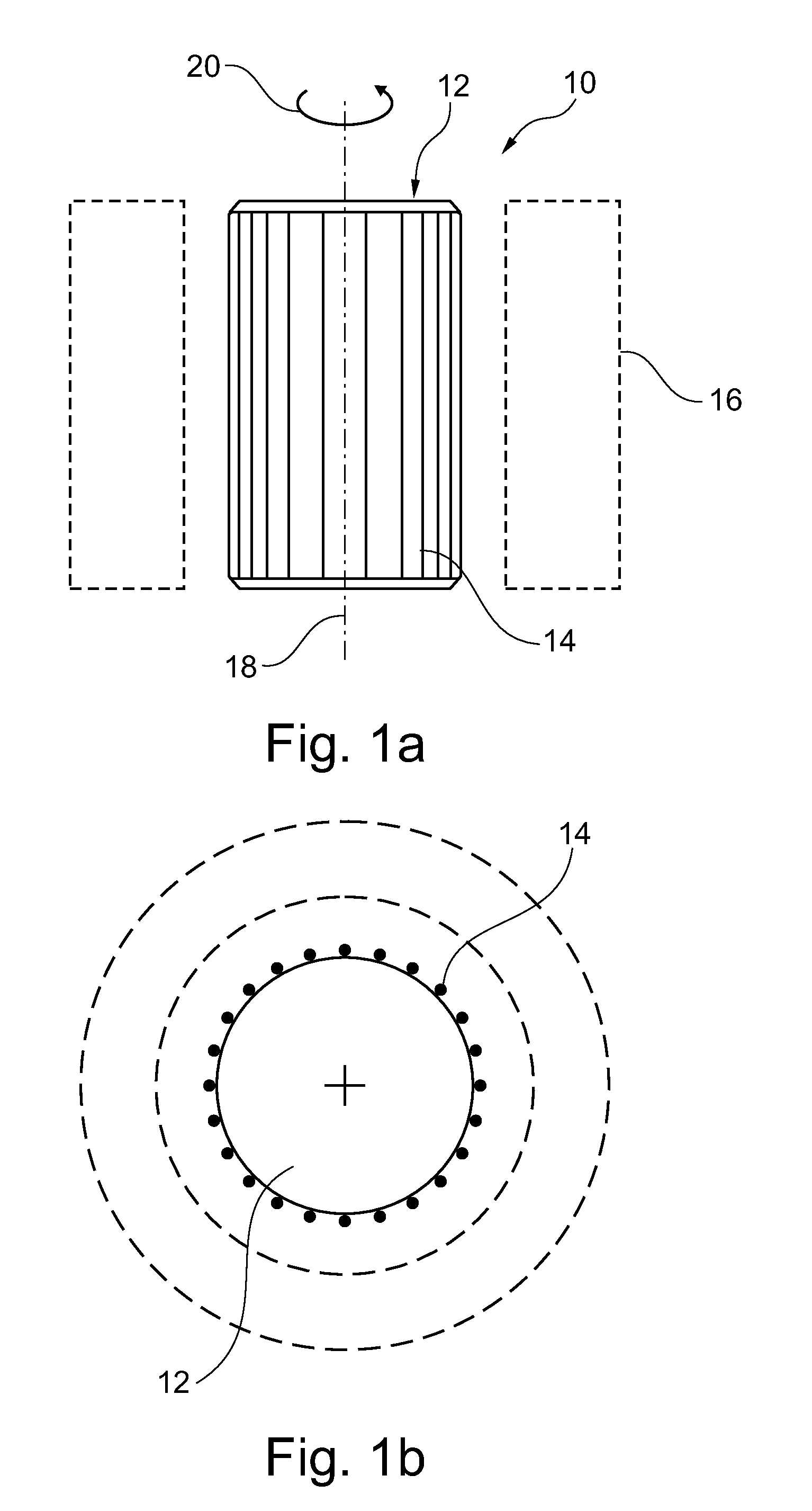
[0046]FIG. 1A shows a side view of a rotor 10 for an X-ray tube. The rotor 10 comprises a rotational structure 12 with a plurality of electrically conducting elements, the ends thereof connected to each other and provided such that an external stator magnetic field generated by a stator induces a current in the electrically conducting elements 14, which current generates a rotor magnetic field to interact with a stator magnetic field. This can also be seen from FIG. 1B showing a top view. The stator is indicated with dotted lines 16 in FIGS. 1A and 1B. At least the plurality of electrically conducting elements 14 is made from carbon composite based material.

[0047]Further, an axis of rotation 18 is indicated together with a rotational arrow 20 indicating the direction of rotation.

[0048]It is noted that the electrically conducting elements 14 are indicated with lines parallel to the axis of rotation, whereas, according to the present invention, also lines inclined to the axis of rotat...


PUM


Abstract

The present invention relates to a rotor for an X-ray tube. In order to provide further possibilities for weight reduction in X-ray tubes for providing an increase of rotation frequency, a rotor (10) for an X-ray tube is provided, comprising a rotational structure (12) with a plurality of electrically conducting elements (14), the ends thereof connected to each other and provided such that an external stator magnetic field generated by a stator induces a current in the electrically conducting elements, which current generates a rotor magnetic field to interact with the stator magnetic field. At least the plurality of electrically conducting elements is made from carbon composite based material.

Description

FIELD OF THE INVENTION[0001]The present invention relates to a rotor for an X-ray tube, to an X-ray tube, to an X-ray imaging system, to a method for rotating an anode of an X-ray tube and to a computer program element as well as to a computer readable medium.BACKGROUND OF THE INVENTION[0002]For driving a rotatable anode of an X-ray tube, a stator is provided which induces a voltage into a rotor coupled to the anode. Upon inducing a voltage into the rotor, for example made out of copper, a magnetic field is generated which interacts with the magnetic field of the stator. However, it has been shown that the thermal mechanical properties of copper also provide a limitation to a lower rotation frequency range. Further, due to increased demands for the field of computer tomography, for example for providing higher scanning frequencies, also weight reduction of the X-ray tube has become increasingly important. The anode disc may thus be provided at least partially with lightweight materi...

Claims


Application Information

Patent Timeline
IPC IPC(8): H02K3/02H01J35/10
CPCH01J35/103H02K3/02H01J2235/1026H01J35/1017
Inventor CHROST, WOLFGANG
Owner KONINKLJIJKE PHILIPS NV
Why Eureka
Try Eureka