
Endoscopic instrument
a technology of endoscopic instruments and endoscopes, which is applied in the field of endoscopic instruments, can solve the problems of difficulty in mustering the necessary force in the tool, and achieve the effect of simple construction and inexpensive manufactur
Patent Information
- Authority / Receiving Office
- US · United States
- Patent Type
- Applications(United States)
- Current Assignee / Owner
- Publication Date
- 2015-05-07
Smart Images
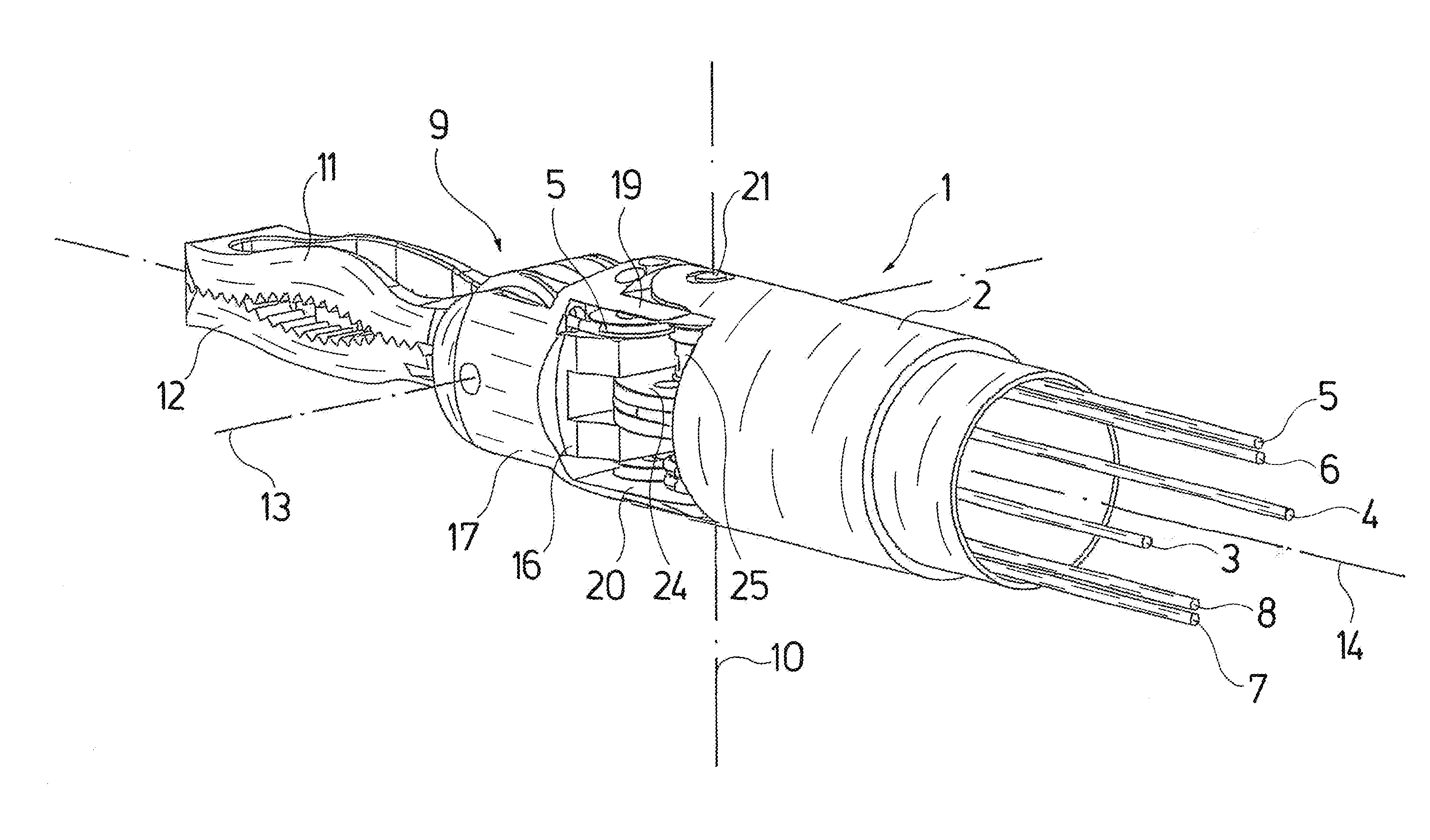
Figure 1 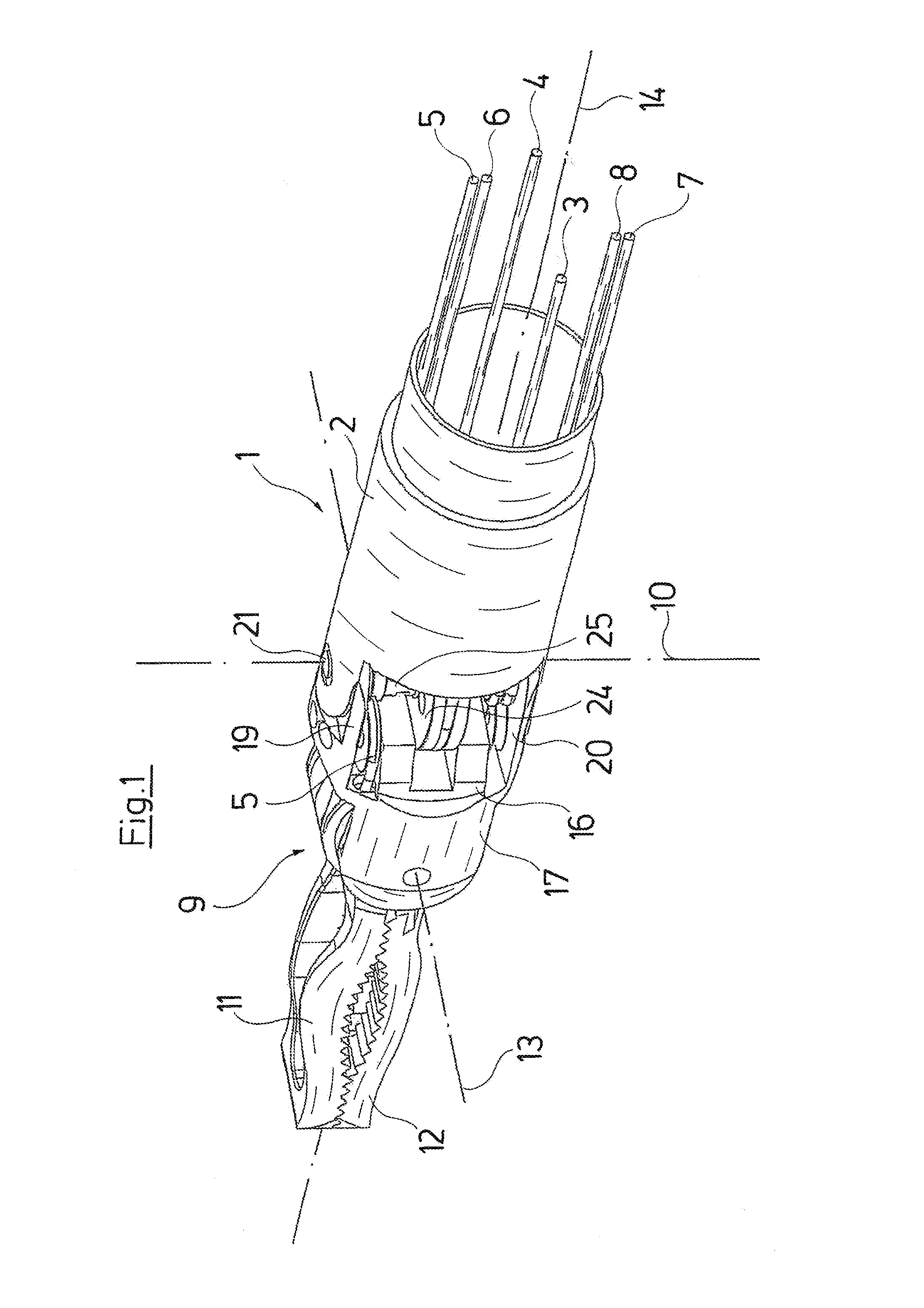
Figure 2 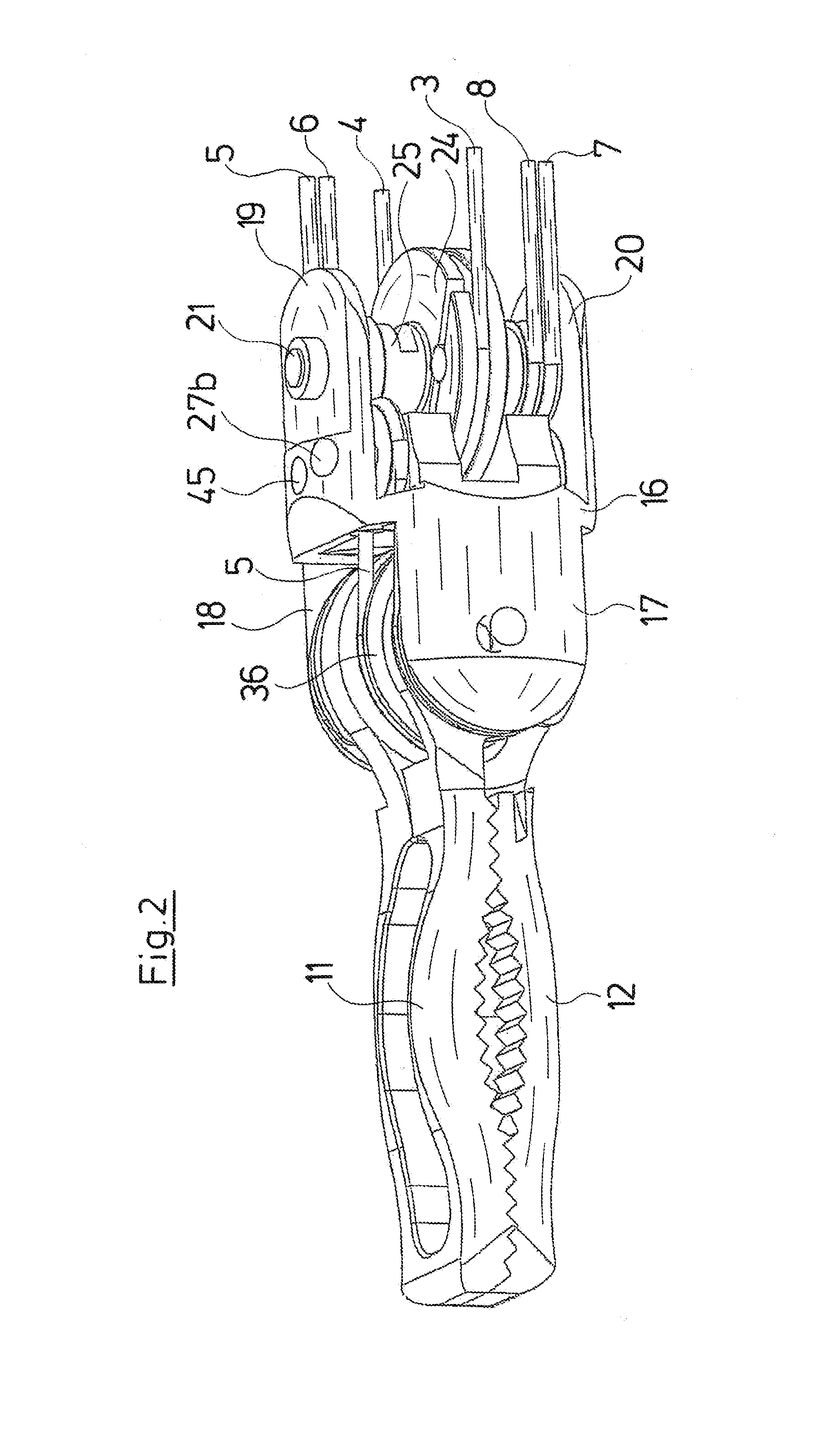
Figure 3
Abstract
Description
CROSS REFERENCE TO RELATED APPLICATIONS
[0001] This application is a United States National Phase Application of International Application PCT / EP2013 / 063865 filed Jul. 1, 2013 and claims the benefit of priority under 35 U.S.C. §119 of German Patent Application DE 10 2012 212 510.8 filed Jul. 17, 2012, the entire contents of which are incorporated herein by reference.FIELD OF THE INVENTION
[0002] The invention relates to an endoscopic instrument with a shank and with an instrument head, which is arranged at the distal shank end and which comprises a tool with two jaw parts which are pivotable to one another and which can be controlled from the proximal instrument end via a pull elements led in the shank, wherein at least one jaw part comprises two curved disks, each of which is engaged by a pull element.BACKGROUND OF THE INVENTION
[0003] Endoscopic instruments of this type, which comprise an instrument head with a tool having two jaw parts pivotable to one another, are applied nowadays in ...
Examples
Embodiment Construction
[0039]With regard to the endoscopic instrument according to the invention, only the distal instrument part is hereinafter described and represented. The longitudinally extended shank as well as the proximal design, be it as a handle for the direct manual actuation by the operator or as a robotic connection as is known with the instrument known from U.S. Pat. No. 6,312,435 B1 is counted as belonging to the general state of the art and is not the subject matter of the present invention.
[0040]Shown in FIG. 1 is the distal shank end 1 as well as the pull means led through the shank 2, in the form of pull wires 3-8 which are led through the shank 2 up to the proximal end and are fastened there via levers, rollers or likewise, for the purpose of applying pull forces. Thereby, the pull wires 3 and 4 serve for pivoting the instrument head 9 about a pivot axis 10, with respect to the distal shank end 1. The pull wires 5 and 6 serve for pivoting the jaw part 11 of a forceps jaw which is at th...