Method for determining pitches of cooling pins for a pneumatic tire and pneumatic tire including cooling pins arranged by the same

a technology of pneumatic tires and cooling pins, which is applied in vehicle tyre testing, instruments, roads, etc., can solve the problems of reducing the lifespan of each component, reducing the heat dissipation performance of rubber which is a major component of the tire, and generating relative high temperature heat from the tire mounted on the vehicle. , to achieve the effect of improving the heat dissipation performance of the sidewall, reducing air flow noise, and improving the quality of the tir

Inactive Publication Date: 2015-05-14
KUMHO TIRE CO INC
View PDF9 Cites 7 Cited by
  • Summary
  • Abstract
  • Description
  • Claims
  • Application Information

AI Technical Summary

Benefits of technology

[0011]In consideration of the above-described circumstances, it is an object of the present invention to provide a method for determining pitches of cooling pins for a pneumatic tire and properly arranging the determined cooling pins in such a manner that, in order to improve heat dissipation effect of the sidewall in which a large amount of heat is generated due to a bending and stretching motion during driving, a plurality of cooling fins of heat dissipating protrusions are formed on a surface of a sidewall, so that the heat dissipation performance of the sidewall may be improved and an airflow noise generated by a high speed air may be decreased, as well as a pneumatic tire including the cooling pins arranged by the same with reduced air resistance by increasing turbulence due to the high speed air.
[0021]According to the present invention, it is possible to improve heat dissipation performance of the sidewall by properly arranging cooling fins thereof, and decrease the air flow noise generated by collapsing of the air due to the cooling fins.
[0022]That is, according to the present invention, it is possible to improve the quality of tire and driving stability by converting a flow of air generated by rotation of a tire during driving into turbulence so as to cool the sidewall of the tire and reduce the air flow noise thereof. In addition, when the run-flat tire travels in an emergency situation, it is possible to improve the driving performance of the tire in emergency driving by increasing heat dissipation performance in the sidewall.

Problems solved by technology

Further, relatively high temperature heat is generated from the tire mounted on the vehicle due to a high-speed rotation thereof or friction with the road surface.
However, rubber which is a major component of the tire has a low heat dissipation performance due to the material characteristics thereof.
For this reason, heat generated from the tire is not properly transmitted to an outside, therefore the lifespan of each component may be shortened, and the tire may be separated or ruptured due to a serious deterioration in tire durability.
In this case, heat is generated from the side wall by the continuously repeated large bending and stretching motion and thermal stress is continuously applied to sidewall reinforcing rubber for supporting the tire against load, causing a rupture in the tire.
However, these techniques have a problem that a resonance phenomenon occurs by an airflow noise generated during high speed air collapsing due to the cooling fins, and thereby the noise is significantly increased.
In addition, for a conventional tire, since cooling fins are formed at fixed intervals for reducing heat generation and turbulence regularly generated by the collision of high speed air is insufficient for effectively radiating heat.
That is, if sufficient turbulence is not generated, the air resistance does not easily decrease.

Method used


Image

  • Method for determining pitches of cooling pins for a pneumatic tire and pneumatic tire including cooling pins arranged by the same
  • Method for determining pitches of cooling pins for a pneumatic tire and pneumatic tire including cooling pins arranged by the same
  • Method for determining pitches of cooling pins for a pneumatic tire and pneumatic tire including cooling pins arranged by the same

Examples


first embodiment

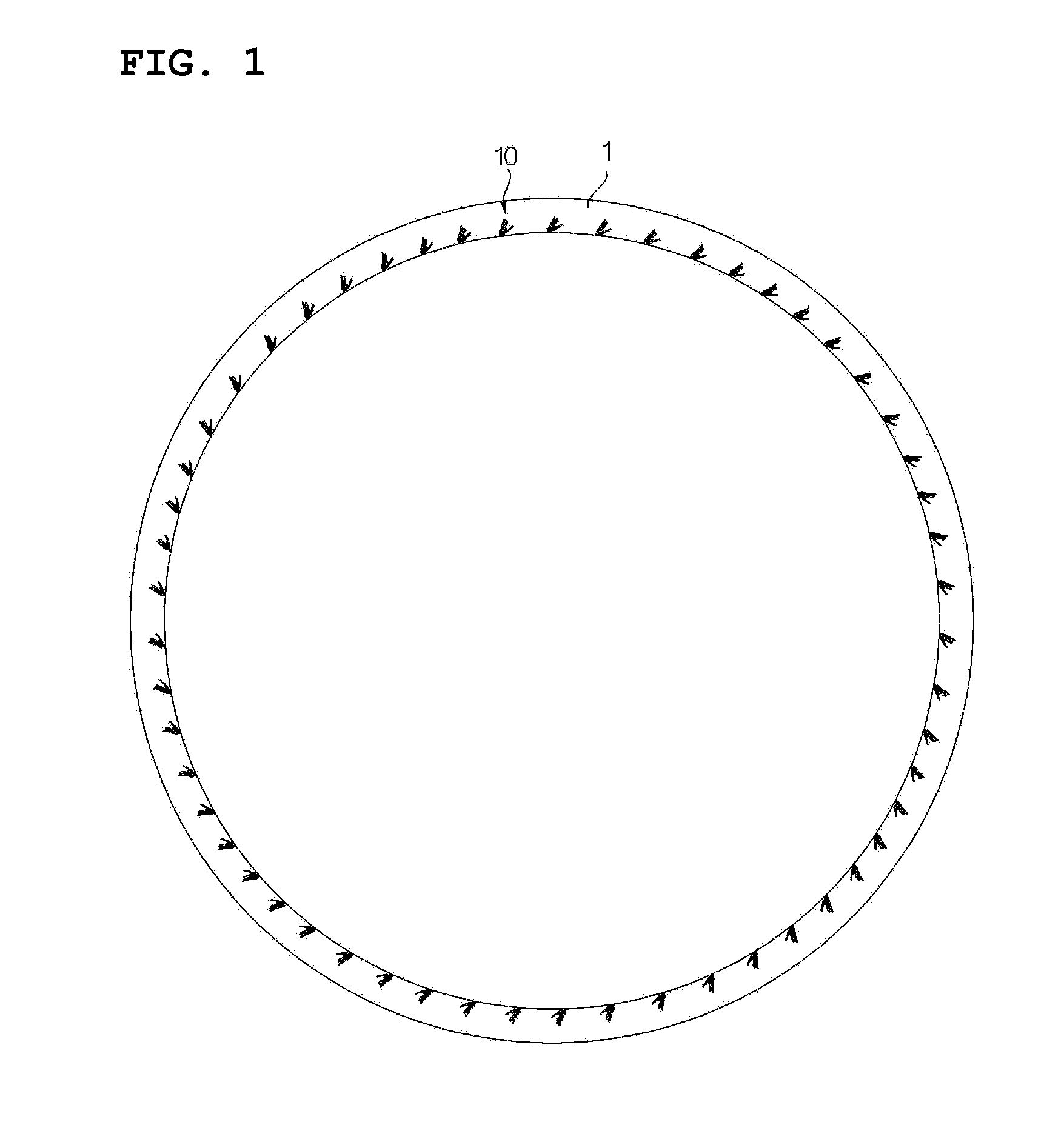
[0042]Next, the cooling fins 10 of a pneumatic tire 1 according to the present invention will be described with reference to FIGS. 1 to 3.

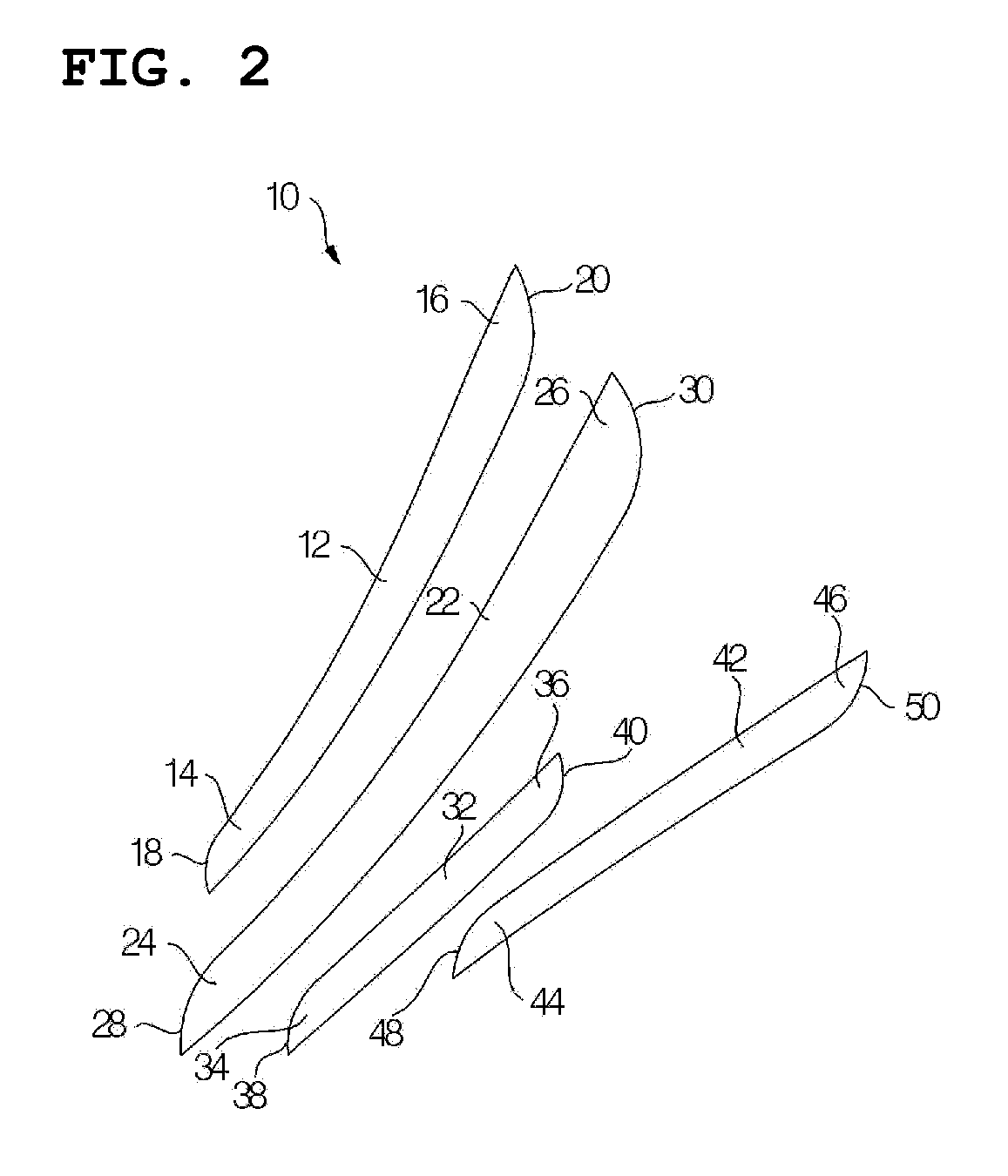
[0043]As shown in FIG. 2, the cooling fin 10 includes a plurality of (four in the present invention) bar-shaped pin unit bodies 12, 22, 32 and 42 which are arranged at predetermined intervals with each other in a circumferential direction of the tire, and are arranged to be inclined toward a radial direction of the tire. At this time, it is preferable that the pin unit bodies 12, 22, 32 and 42 have an inclination angle of 20 to 60° in terms of cooling, and the cooling fin 10 includes two to six pin unit bodies 12, 22, 32 and 42.

[0044]The pin unit bodies 12, 22, 32 and 42 may be formed to incline substantially at 30 to 60° toward the radial direction of the tire. When the pin unit bodies 12, 22, 32 and 42 are formed to incline within the above-described range, air flow from the front flows to outside in a radial direction of the tire.

[0045]Herein, ...

second embodiment

[0049]Next, cooling fins 104 of a pneumatic tire 100 according to the present invention will be described with reference to FIGS. 4 to 7.

[0050]As shown in FIGS. 5 and 6, the cooling fins 104, formed on a surface of a sidewall 102 of the pneumatic tire 100 according to the second embodiment of the present invention, include a first bar part 110 and a second bar part 106 which are connected with each other at an acute angle. Therefore, the cooling fin 104 is formed in a substantially V shape by the first and second bar parts 110 and 106 as a whole. Herein, a V-shaped vertex formed by the first and second bar parts 110 and 106 is disposed to be inclined in the circumferential direction of the tire.

[0051]In addition, the second bar part 106 is formed to be inclined in the radial direction of the tire. As a result, an angle of the second bar part 106 with respect to the radial direction of the tire is smaller than that of the first bar part 110 with respect to the radial direction of the...

third embodiment

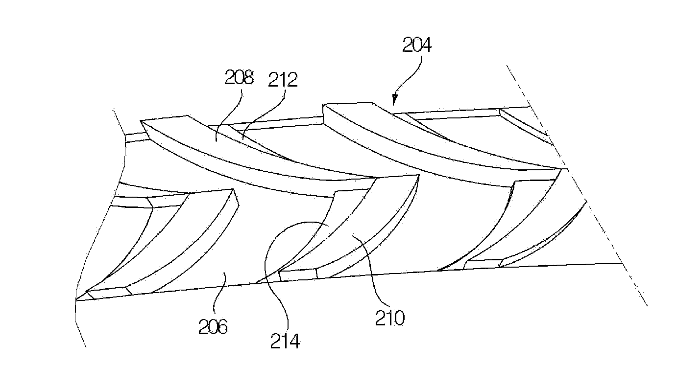
[0055]Finally, cooling fins 204 of a pneumatic tire 200 according to the present invention will be described with reference to FIGS. 8 to 10.

[0056]As shown in FIG. 10, the cooling fins 204, formed on a surface of a sidewall 202 of the pneumatic tire 200 according to the third embodiment of the present invention, include a first protrusion part 208 and a second protrusion part 210 which are connected with each other at an acute angle. Therefore, the cooling fin 204 is formed in a substantially V shape by the first and second protrusion parts 208 and 210 as a whole. Herein, a V-shaped vertex formed by the first and second protrusion parts 208 and 210 is disposed in the circumferential direction of the tire.

[0057]Herein, the first protrusion part 208 and the second protrusion part 210 are formed to be inclined in the radial direction of the tire with incline directions opposite to each other.

[0058]In addition, an end portion of the second bar part 210 is disposed closer to the center o...


PUM


Abstract

Disclosed are a method for determining pitches of cooling pins for a pneumatic tire so that the heat dissipation performance of the sidewall may be improved and an airflow noise generated by a high speed air may be decreased, and a pneumatic tire including the cooling pins arranged by the same. The method for determining pitches of cooling pins for a pneumatic tire, including: selecting a total number of cooling fins, the number of pitch-types, and a size of each pitch; generating a random number and arranging each type of pitch sequentially by the generated random number to produce a random pitch arrangement; Fourier transforming the obtained pitch arrangement to calculate a result value (FT); and repeatedly performing the steps of producing a random pitch arrangement and calculating the FT to determine a pitch arrangement when a change in amplitude of the FT is smallest.

Description

CROSS-REFERENCE TO RELATED APPLICATIONS[0001]This application claims priority to Korean Patent Application Nos. 10-2013-0094144, filed on Aug. 8, 2013, 10-2014-0038574, filed on Apr. 1, 2014 and 10-2014-0038584, filed on Apr. 1, 2014 in the Korean Intellectual Property Office, the entire disclosures of which are incorporated herein by reference.FIELD OF THE INVENTION[0002]The present invention relates to a method for determining pitches of cooling pins for a pneumatic tire and a pneumatic tire including the cooling pins arranged by the same, and more specifically to a method for determining pitches of cooling pins for a pneumatic tire and properly arranging the determined cooling pins in such a manner that, in order to improve heat dissipation effect of a sidewall in which a large amount of heat is generated due to a bending and stretching motion during driving, a plurality of cooling fins of heat dissipating protrusions are formed on a surface of the sidewall, so that the heat diss...

Claims


Application Information

Patent Timeline
Patent Type & Authority Applications(United States)
IPC IPC(8): G01M17/02B60C23/18
CPCB60C23/18G01M17/02B60C11/0318B60C13/02
Inventor PARK, WOO-CHEOL
Owner KUMHO TIRE CO INC
Why Eureka
Try Eureka