Vibration-resistant rotation rate sensor

a technology of rotation rate sensor and vibration resistance, which is applied in the direction of acceleration measurement using interia force, instruments, devices using electric/magnetic means, etc., can solve the problems of comparatively high sensitivity of known rotation rate sensors to external interference, and achieve the effect of improving vibration resistance and reliable operation of the rotation rate sensor

Active Publication Date: 2015-05-14
ROBERT BOSCH GMBH
View PDF2 Cites 19 Cited by
  • Summary
  • Abstract
  • Description
  • Claims
  • Application Information

AI Technical Summary

Benefits of technology

[0004]Therefore, an object of the present invention is to provide a rotation rate sensor having improved vibration resistance, thereby ensuring a more reliable operation of the rotation rate sensor, even under the influence of external interferences.

Problems solved by technology

However, known rotation rate sensors have a comparatively high sensitivity to external interferences, an interfering signal influencing the function of the rotation rate sensor being generated in the rotation rate sensor.

Method used


Image

  • Vibration-resistant rotation rate sensor
  • Vibration-resistant rotation rate sensor
  • Vibration-resistant rotation rate sensor

Examples


Embodiment Construction

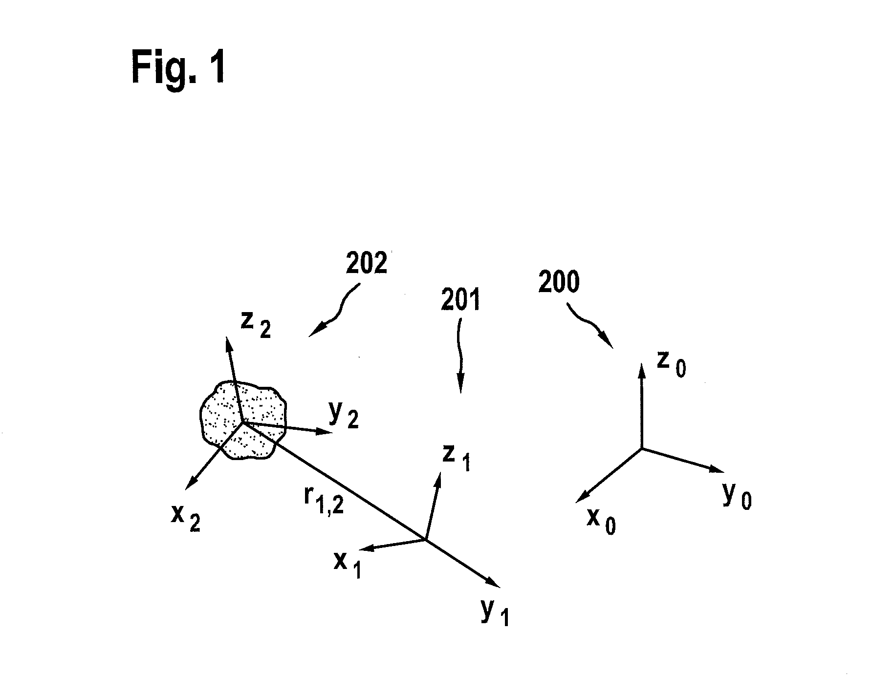
[0028]FIG. 1 shows a schematic view of a reference model. Represented here are the basic correlations of a relative movement of a seismic mass in the system of seismic masses (reference numeral 202) in a reference system (reference numeral 201), the movement of which is to be measured relative to an inertial system 200. The relative movement of a seismic mass with body-fixed system 202 (coordinates x2, y2, z2) in reference system 201 (coordinates x1, y2, z1) is represented, which, in turn, moves arbitrarily in inertial system 200 (coordinates x0, y0, z0).

[0029]The acceleration of the seismic mass is composed of a Coriolis acceleration, a linear acceleration, a rotational acceleration and a centrifugal acceleration. It was found that the linear acceleration component and the rotational acceleration component have a dominant influence on the respective measuring signal as compared to the centrifugal acceleration component. Advantageously according to the present invention, the compens...


PUM


Abstract

A rotation rate sensor includes a substrate having a main extension plane and multiple seismic masses, in which for each seismic mass the following applies: the seismic mass is drivable at a drive oscillation, which occurs along a drive direction situated parallel to the main extension plane, the seismic mass is deflectable along two different deflection directions, each direction being perpendicular to the drive direction, the rotation rate sensor being configured to generate detection signals as a function of detected deflections of the seismic masses, one detection signal of the detection signals being associated with each deflection direction of the seismic masses, the rotation rate sensor being configured so that a linear, rotational and centrifugal acceleration of the rotation rate sensor are compensated with respect to at least one rotation axis of the rotation rate sensor through compensation in each case of two corresponding detection signals of the detection signals.

Description

RELATED APPLICATION INFORMATION[0001]The present application claims priority to and the benefit of German patent application no. 10 2013 223 227.6, which was filed in Germany on Nov. 14, 2013, the disclosure of which is incorporated herein by reference.FIELD OF THE INVENTION[0002]The present invention is directed to a rotation rate sensor.[0003]Such rotation rate sensors are generally known. However, known rotation rate sensors have a comparatively high sensitivity to external interferences, an interfering signal influencing the function of the rotation rate sensor being generated in the rotation rate sensor. Such interferences are, for example, accelerations of the rotation rate sensor.SUMMARY OF THE INVENTION[0004]Therefore, an object of the present invention is to provide a rotation rate sensor having improved vibration resistance, thereby ensuring a more reliable operation of the rotation rate sensor, even under the influence of external interferences.[0005]The rotation rate sen...

Claims


Application Information

Patent Timeline
Patent Type & Authority Applications(United States)
IPC IPC(8): G01C19/5705
CPCG01C19/5705G01C19/5733G01C19/5726G01C19/574
Inventor NEUL, REINHARD
Owner ROBERT BOSCH GMBH
Why Eureka
Try Eureka