System for removal of contaminants in water

a technology for water contaminants and water systems, applied in water cleaning, water separation processes, swimming pools, etc., can solve the problems of contaminating water, affecting the placement of water bodies, and affecting the effect of water quality, so as to facilitate the placement

a technology for water contaminants and water systems, applied in water cleaning, water separation processes, swimming pools, etc., can solve the problems of contaminating water, affecting the placement of water bodies, and affecting the effect of water quality, so as to facilitate the placement

US20150129480A1Active Publication Date: 2015-05-14PASOZ LOUIS

Image

  • System for removal of contaminants in water
  • System for removal of contaminants in water
  • System for removal of contaminants in water

Examples


Embodiment Construction

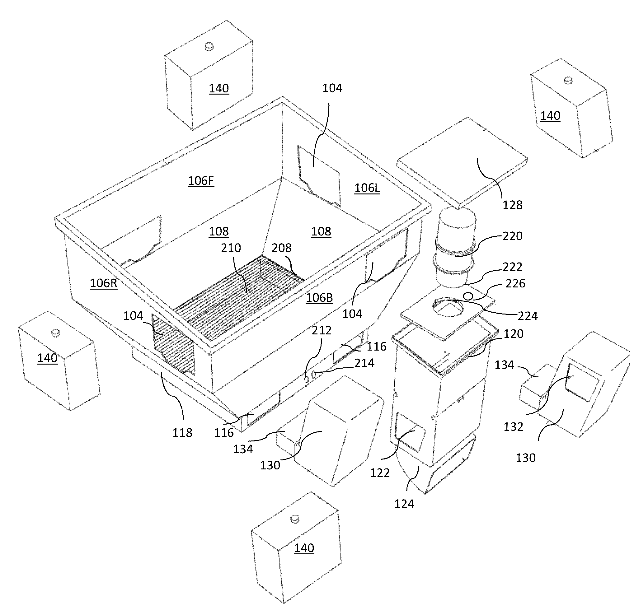
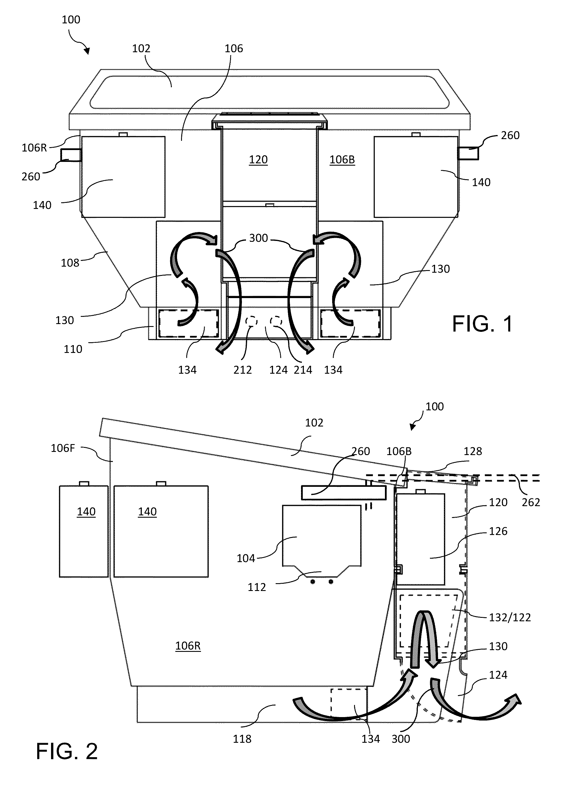
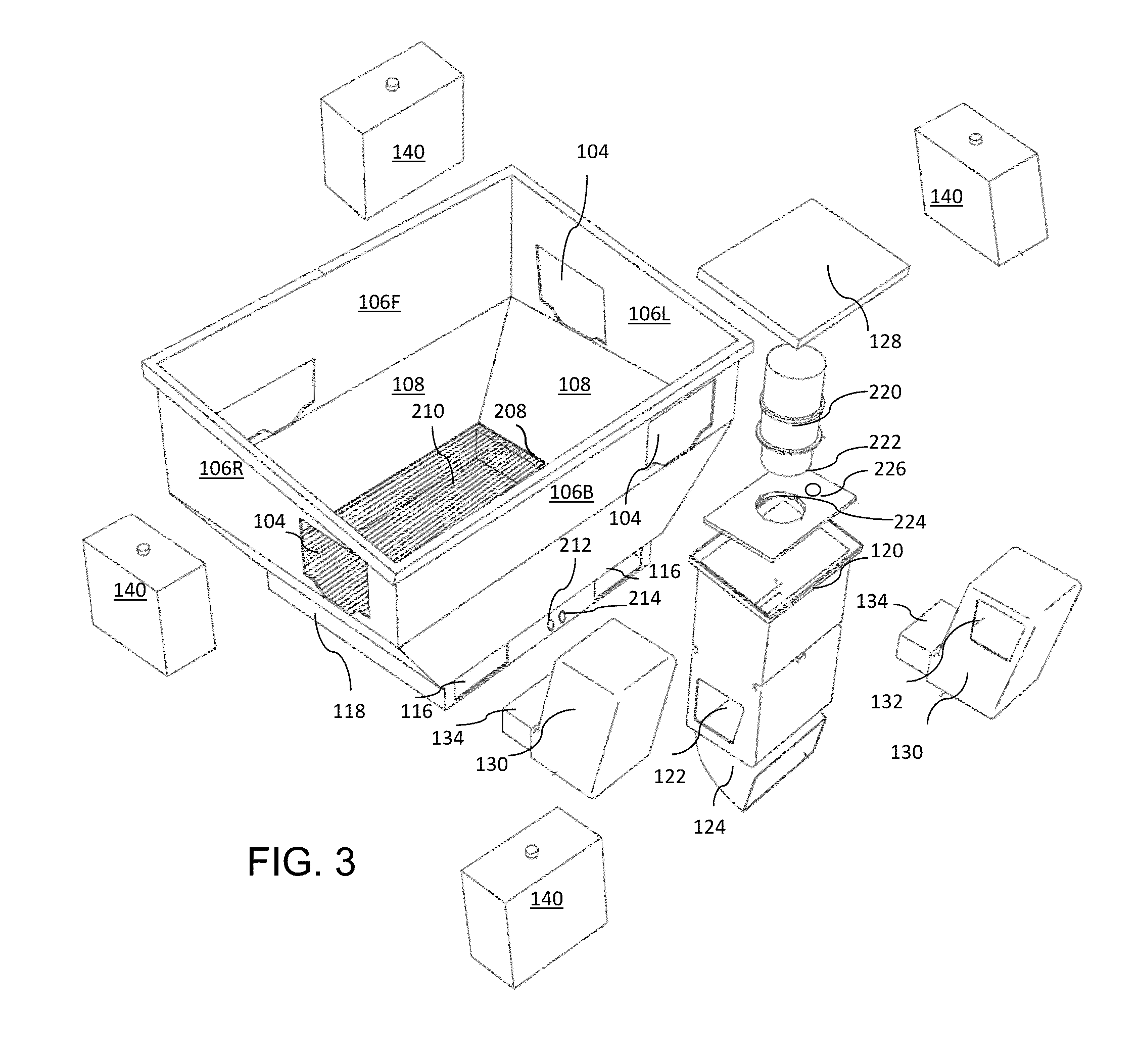
[0019]As illustrated in FIGS. 1-3, the skimmer assembly 100 for removal of contaminants from water comprises a generally rectangular enclosure 106 with an openable lid 102 and at least one inlet 104 near the top for admitting water into the interior of the enclosure. At least one intake module 130 is attached to the enclosure with a conduit 134 at its lower portion extending through an opening 116 near the bottom of the enclosure. In the illustrated embodiment, two inlet modules 130 are shown. An upper port 132 formed on one side of the intake module. A pump module 120 is attached to the outer surface of the enclosure adjacent to the intake module(s). The pump module 120 has a side port 122 that matches the upper port(s) 132 of the intake module 130 so that the pump module 120 and the intake module 130 are in fluid communication through the ports 122 and 132. The pump module 120 has an outlet channel 124 at its lower portion to direct water away from the enclosure.

[0020]The enclosur...


PUM

PropertyMeasurementUnit
vacuumaaaaaaaaaa
sizeaaaaaaaaaa
areaaaaaaaaaaa

Abstract

An apparatus for removal of contaminants from water includes an openable enclosure with one or more inlet openings through the sides for admitting water and debris into the enclosure. Intake modules attached to the outer surface of the enclosure draw water from the enclosure through an intake conduit and out an upper port in the side of the intake module. A pump module adjacent to the intake module has a side port corresponding to the upper port of the intake module so that water is drawn by a pump from the intake module and exhausted through an outlet channel of the pump module. A snorkel attached to the pump module with its lower end located adjacent to the pump propeller draws air down into the snorkel and into a fitting disposed below the pump propeller for injection into the enclosure.

Description

RELATED APPLICATIONS[0001]This application claims the benefit of the priority of U.S. Provisional Application No. 61 / 902,817, filed Nov. 12, 2013.BACKGROUND OF THE INVENTION[0002]Bodies of water near populated areas are commonly subject to pollution from both chemical and solid waste. Considerable effort has been addressed to the removal of oil slicks or other chemical films that float on the water surface. Among such efforts are the floating weirs of McHugh, Jr. (U.S. Pat. No. 4,405,458 issued Sep. 20, 1983) and Wessels (U.S. Pat. No. 4,802,592 issued Feb. 7, 1989). Both of these systems are remote from the pumping unit, being connected by a suction hose, and are similar to well-known pool cleaners. Another system is that of Shubert (U.S. Pat. No. 4,618,833 issued Jul. 22, 1986) which is a floating trough for removal of effluent fluid at a predetermined level beneath the surface of the water. While advances have been addressed to liquid separation, solid waste is still primarily de...

Claims


Application Information

Patent Timeline
14 May 2015
Publication
US20150129480A1
IPC
C02F1/40; E04H4/16; E02B15/10
CPC
C02F1/40; E02B15/10; C02F2201/002; C02F2103/007; E04H4/16; B01D21/0027; B01D21/2433; B01D21/307
Inventors
PASOZ, LOUIS