
Vibration damping device

Active Publication Date: 2015-05-14
TOKAI RUBBER IND LTD
View PDF3 Cites 27 Cited by
  • Summary
  • Abstract
  • Description
  • Claims
  • Application Information

AI Technical Summary

Benefits of technology

The invention is a new kind of device used to dampen vibrations. The problem it aims to solve is to better position the bracket and mounting member while achieving a strong positioning effect through fitting.

Problems solved by technology

However, with the vibration damping device having this kind of constitution for which the bracket member is fit into and attached to a tube shaped first mounting member, it is easy to have the problem of the bracket member falling out from the first mounting member.
However, when using the constitution noted in JP-A-2012-036971, while the first mounting member and bracket member positioning effect by the locking action can be expected, there is the problem that the positioning effect is decreased due to fitting of the bracket member to the first mounting member.
However, one of the engaged part and the engaging part is made to be put into the other and locked, and with the part formed by the engaged part and the engaging part, as described above, since there is a decrease in the positioning effect by the fitting, there was the risk of not having a sufficient positioning effect to prevent the bracket member from falling out of the first mounting member.

Method used


Image

  • Vibration damping device
  • Vibration damping device
  • Vibration damping device

Examples


Embodiment Construction

[0037]Following, we will describe an embodiment of the present invention while referring to the drawings.

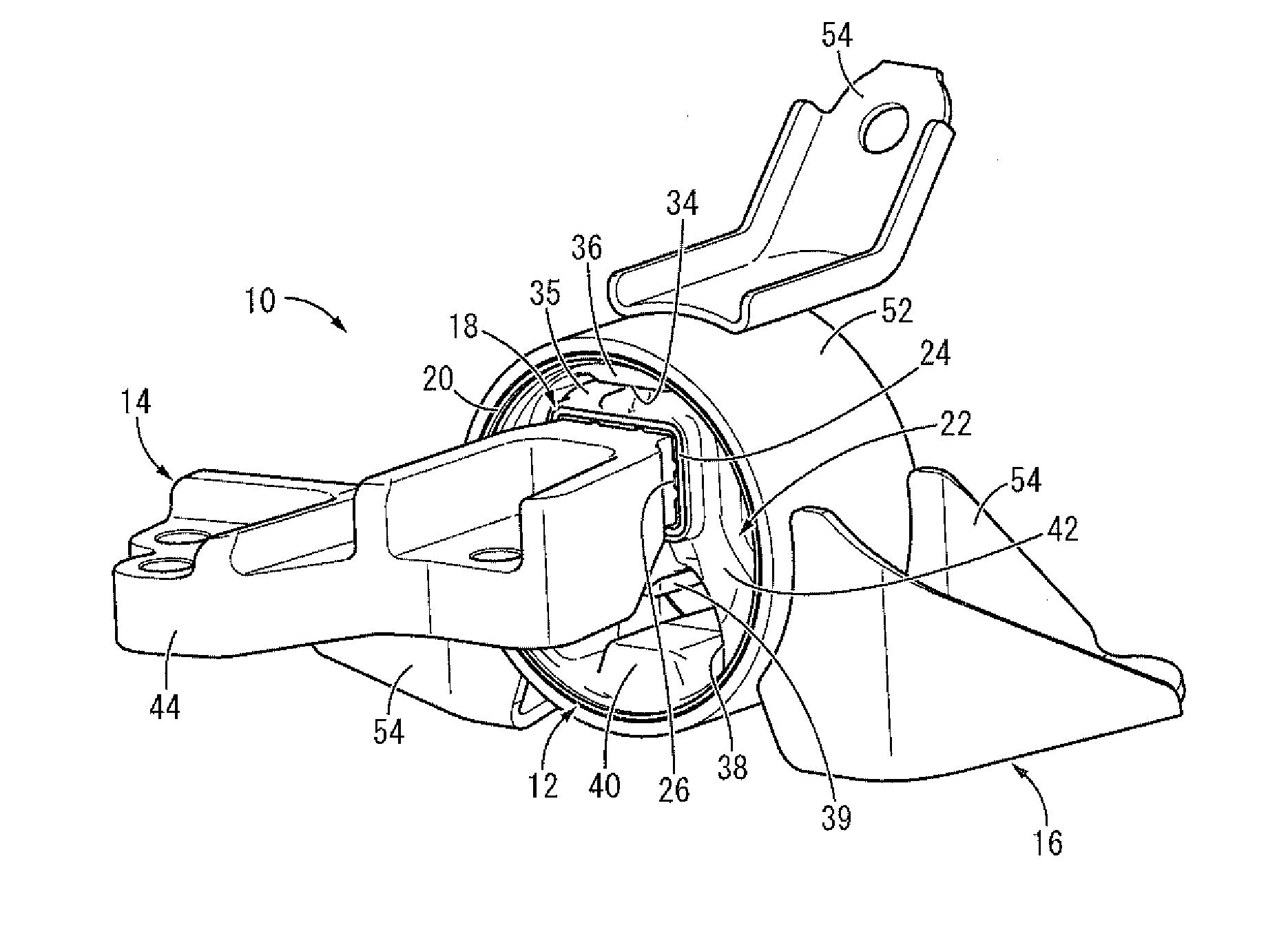
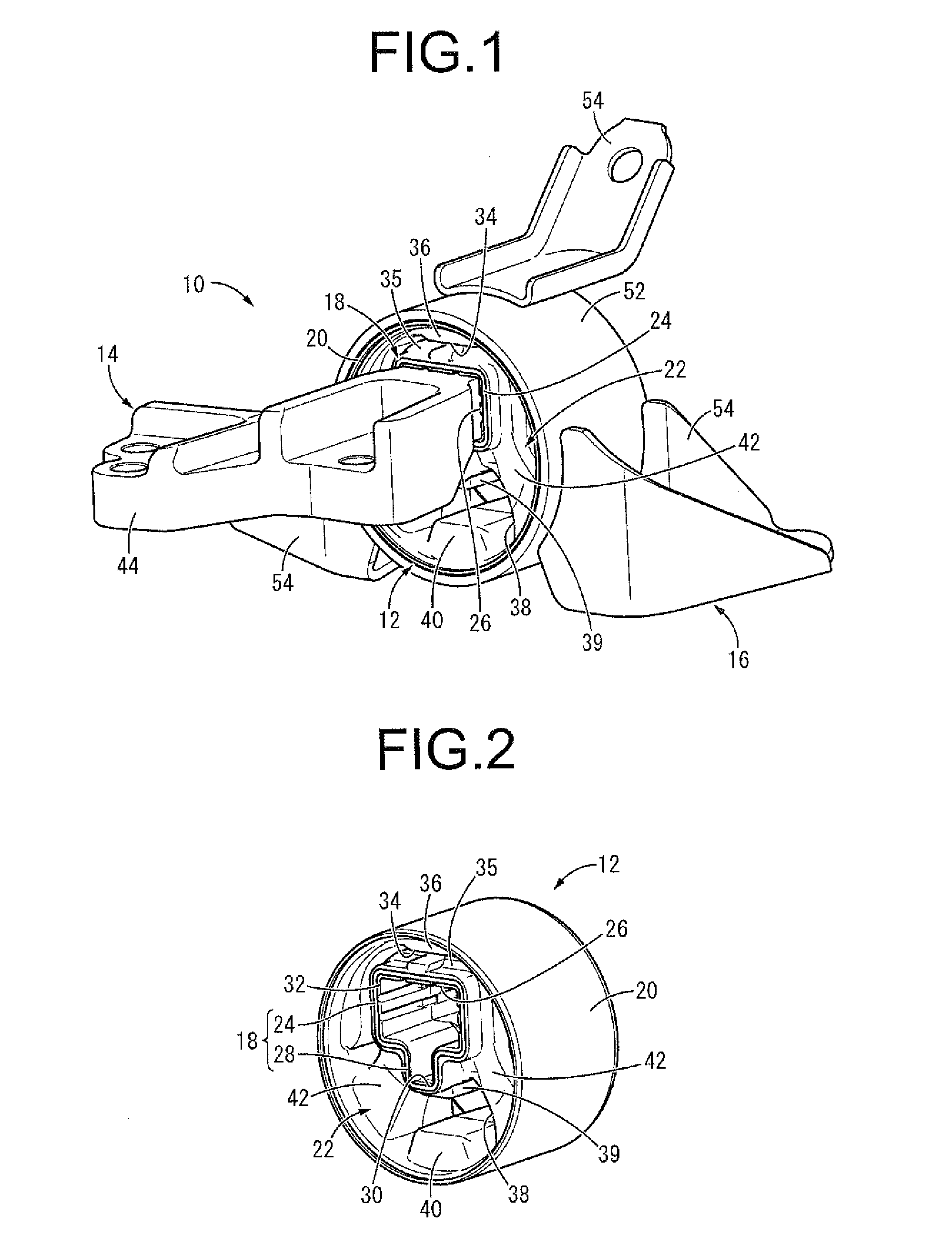
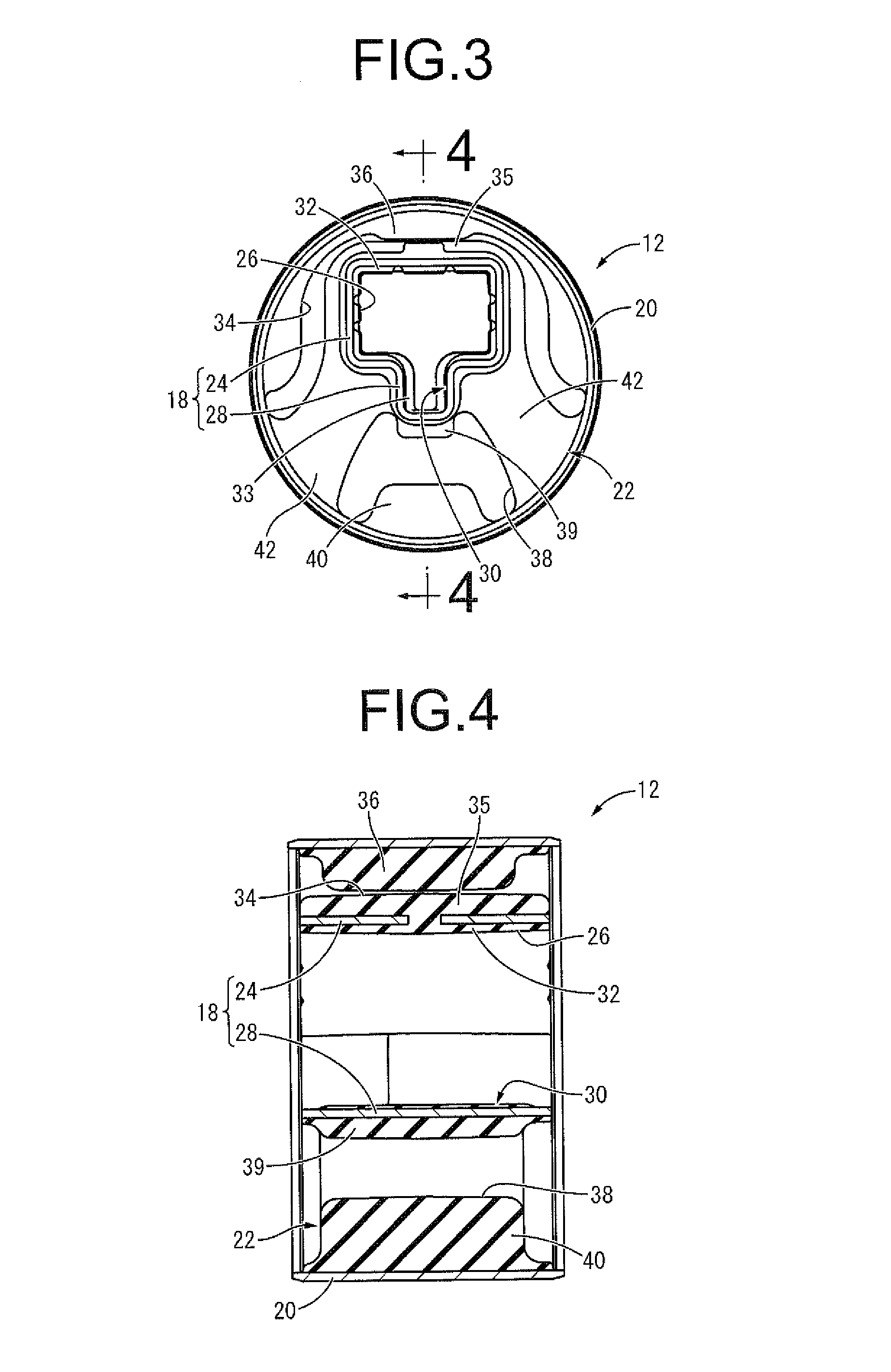
[0038]FIG. 1 shows an engine mount 10 of an automobile as a first embodiment of a vibration damping device constituted according to the present invention. This engine mount 10 is constituted with an inner bracket 14 as a bracket member and an outer bracket 16 attached to a mount main body 12. Then, the inner bracket 14 is attached to a power unit (not illustrated), and the outer bracket 16 is attached to a vehicle body (not illustrated), and the power unit is connected with vibration damping to the vehicle body via the engine mount 10. With the description hereafter, the vertical direction as a rule means the vertical direction in FIG. 3 which is the main vibration input direction.

[0039]In more detail, as shown in FIG. 2 to FIG. 4, the mount main body 12 has a structure for which a first mounting member 18 and a second mounting member 20 are elastically connected by a main rubber...


PUM


Abstract

A vibration damping device including: first and second mounting members; a main rubber elastic body elastically connecting the two members; and a bracket member fit into the first mounting member. A projecting part projects outward from a circumference of the first mounting member, and includes a locking groove whose inner surface is covered by a rubber coating layer and has a locking part on its side wall inner surface. An engaging projection projecting from the bracket member is fit into the locking groove, and a projection tip surface of the engaging projection is abutted on a bottom wall inner surface of the locking groove. A side surface of the engaging projection is locked to the locking part so as to constitute a positioning member that positions the first mounting member and the bracket member to each other.

Description

INCORPORATED BY REFERENCE[0001]The disclosure of Japanese Patent Application No. 2012-213140 filed on Sep. 26, 2012, including the specification, drawings and abstract is incorporated herein by reference in its entirety. This is a Continuation of International Application No. PCT / JP2013 / 075551 filed on Sep. 20, 2013.BACKGROUND OF THE INVENTION[0002]1. Field of the Invention[0003]The present invention relates to a vibration damping device used for an engine mount of an automobile or the like, and particularly relates to a vibration damping device for which a bracket member is fit and mounted in a tube shaped first mounting member.[0004]2. Description of the Related Art[0005]From the past, known are vibration damping devices interposed between members constituting the vibration transmission system as one type of vibration damping connecting body or vibration damping support body for vibration damping connecting those members to each other. The vibration damping device has a first moun...

Claims


Application Information

Patent Timeline
IPC IPC(8): B60K5/12F16F15/08
CPCF16F15/08B60K5/1208F16F1/3842F16F1/3863
Inventor OKANAKA, TAKEHIROKOGA, SATOKI
Owner TOKAI RUBBER IND LTD
Features
  • Generate Ideas
  • Intellectual Property
  • Life Sciences
  • Materials
  • Tech Scout
  • Unparalleled Data Quality
  • Higher Quality Content
  • 60% Fewer Hallucinations
Learn More