Adaptive dynamic range imaging

a dynamic range and image sensor technology, applied in the field of image processing, can solve the problems of limited contrast range, complicated design of such compact camera/video system, and governed lower limit of dynamic range of image sensor, and achieve the effect of slowing down capture and strong motion artifacts

Inactive Publication Date: 2015-05-14
NVIDIA CORP
View PDF12 Cites 55 Cited by
  • Summary
  • Abstract
  • Description
  • Claims
  • Application Information

AI Technical Summary

Benefits of technology

[0006]Embodiments of the present invention provide solutions to the challenges inherent in high-dynamic range imaging that extends a sensor's dynamic range in exchange for a slower capture and strong motion artifacts. In a method according to one embodiment of the present invention, a method for adaptive dynamic range imaging is disclosed, in which, a scene's dynamic range is calculated. An adaptive dynamic range is selected that is no more than the scene's dynamic range. Scene data is captured with the selected adaptive dynamic range.

Problems solved by technology

However, the design of such compact camera / video systems is complicated by a limited contrast range, also referred to as dynamic range.
Furthermore, a lower limit of a dynamic range for an image sensor is governed by read noise and quantization.
For example, a short exposure time may prevent bright areas of a scene from saturating corresponding pixel sites; however, detailed information in darker areas of the scene may be lost because the signal received from these areas is too weak to register at all.
However, such increases in dynamic range come with various tradeoffs, typically to resolution, signal-to-noise ratio (SNR), sharpness, motion artifacts, color and / or speed, etc.
These difficulties with capturing multiple images for reconstruction into a single image are exacerbated by the fact that the sensors need to be continuously capturing images for video.

Method used


Image

  • Adaptive dynamic range imaging
  • Adaptive dynamic range imaging
  • Adaptive dynamic range imaging

Examples


Embodiment Construction

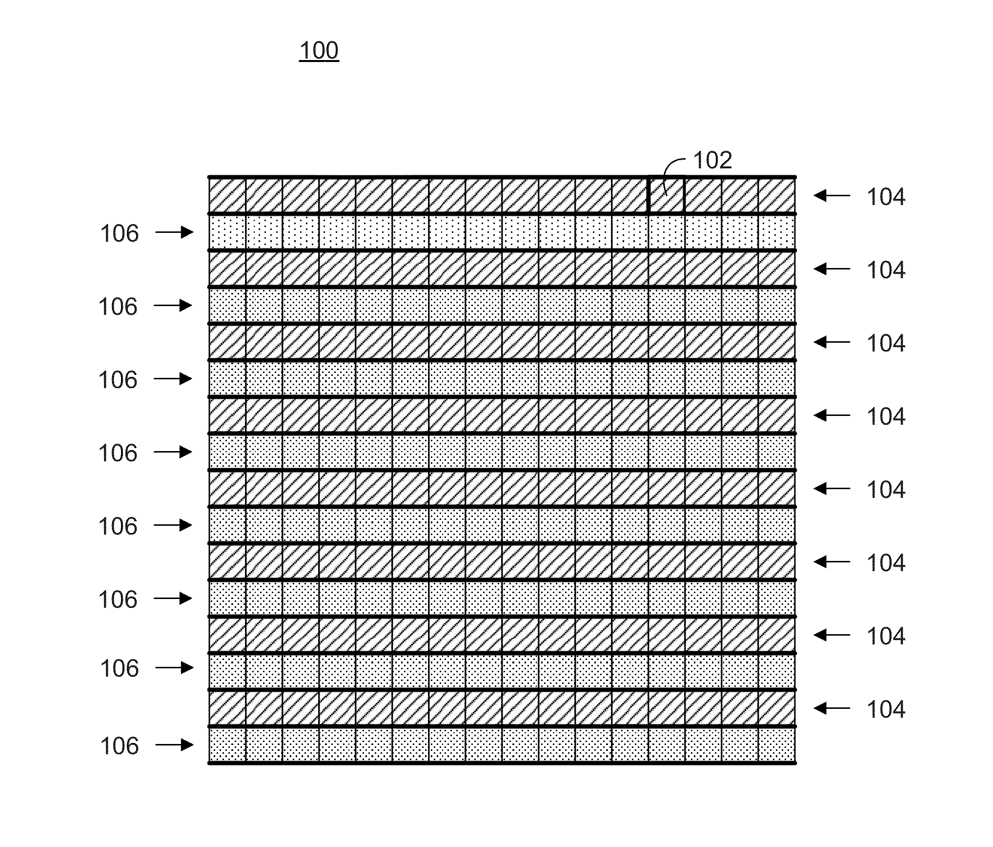
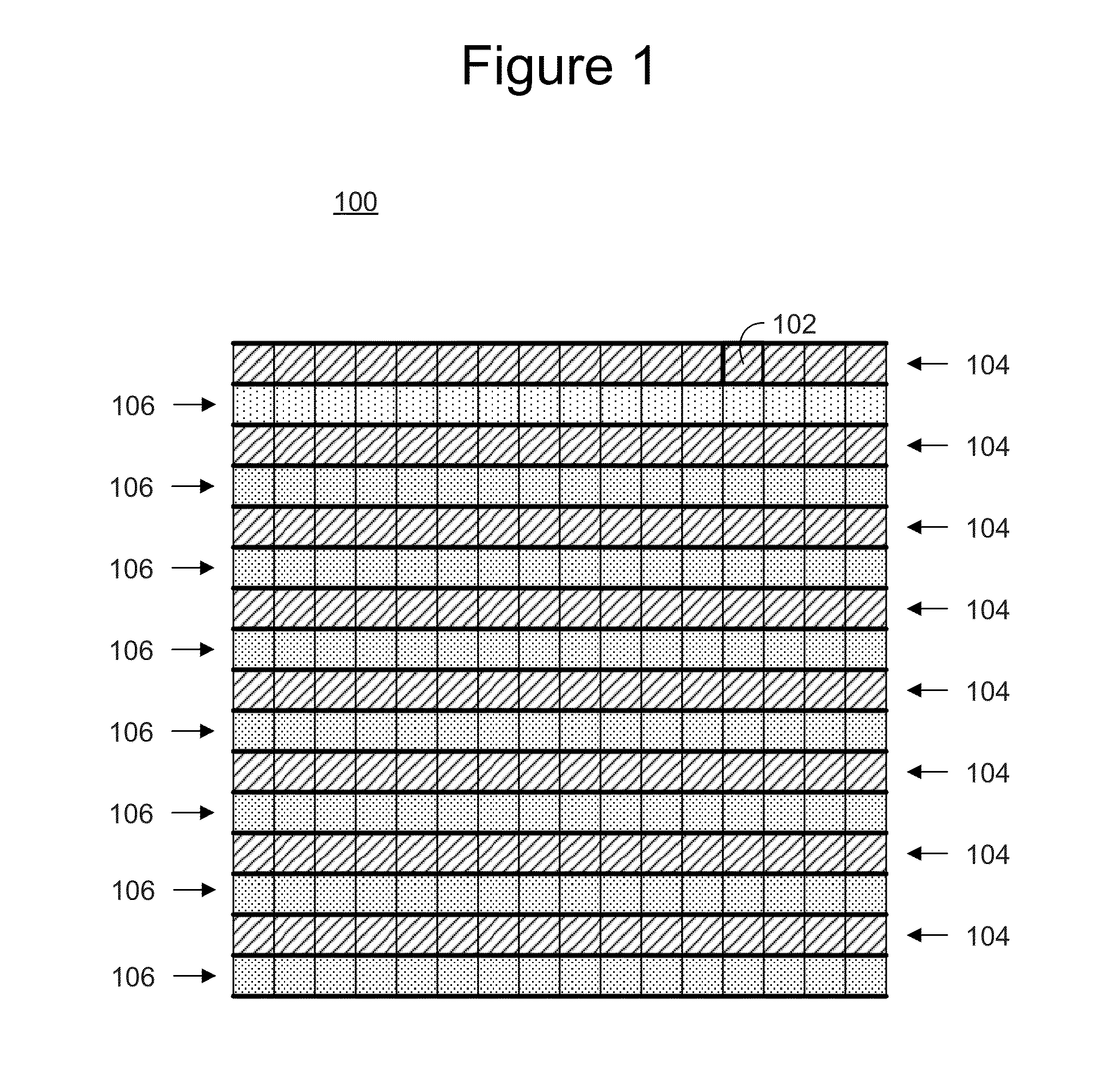
[0015]Reference will now be made in detail to the preferred embodiments of the present invention, examples of which are illustrated in the accompanying drawings. While the invention will be described in conjunction with the preferred embodiments, it will be understood that they are not intended to limit the invention to these embodiments. On the contrary, the invention is intended to cover alternatives, modifications and equivalents, which may be included within the spirit and scope of the invention as defined by the appended claims. Furthermore, in the following detailed description of embodiments of the present invention, numerous specific details are set forth in order to provide a thorough understanding of the present invention. However, it will be recognized by one of ordinary skill in the art that the present invention may be practiced without these specific details. In other instances, well-known methods, procedures, components, and circuits have not been described in detail ...


PUM


Abstract

In an apparatus according to one embodiment of the present invention, a video system is disclosed. The video system comprises a pre-processing module, an auto-exposure module, and an image sensor. The image sensor is operable to simultaneously capture a first image at a long exposure and a second image at a short exposure capture. The auto-exposure module is operable to determine an average brightness of a scene for video/image capturing, wherein the determined brightness achieves a desired image quality. The auto-exposure module is further operable to select a dynamic range necessary to preserve desired details in a captured scene. The auto-exposure module is further operable to instruct the image sensor to capture the first image and the second image with a selected exposure ratio to achieve the desired dynamic range. The pre-processing module is operable to combine the first image and the second image into a final image with the desired dynamic range.

Description

TECHNICAL FIELD[0001]The present disclosure relates generally to the field of image processing and more specifically to the field of high-dynamic range image processing.BACKGROUND[0002]Digital photographs and digital video may be captured today using a variety of image sensors (e.g., complementary metal-oxide semiconductor (CMOS) image sensors and charge coupled device (CCD) image sensors. Such image and video capture functionality may be found in mobile devices. However, the design of such compact camera / video systems is complicated by a limited contrast range, also referred to as dynamic range. Furthermore, a lower limit of a dynamic range for an image sensor is governed by read noise and quantization. Even in the absence of read-noise, a charge on a pixel is sampled to a discrete digital value; e.g., a 10-bit value. The charge for a pixel may be digitized using for instance a 10-bit ADC (analog-to-digital converter) to generate a value between 0 and 1023. This means that the brig...

Claims


Application Information

Patent Timeline
Patent Type & Authority Applications(United States)
IPC IPC(8): H04N5/235H04N5/265
CPCH04N5/2355H04N5/2353H04N5/265H04N23/73H04N23/741
Inventor PIEPER, SEAN
Owner NVIDIA CORP
Why Eureka
Try Eureka