Illumination device, and display device
a technology of display device and light guide plate, which is applied in the direction of planar/plate-like light guide, lighting and heating apparatus, instruments, etc., can solve the problems of v-shaped bright lines, difficult to have the light enter the wide light guide plate in a uniform manner, etc., and achieves simple configuration and reduce energy consumption.
- Summary
- Abstract
- Description
- Claims
- Application Information
AI Technical Summary
Benefits of technology
Problems solved by technology
Method used
Image
Examples
embodiment 1
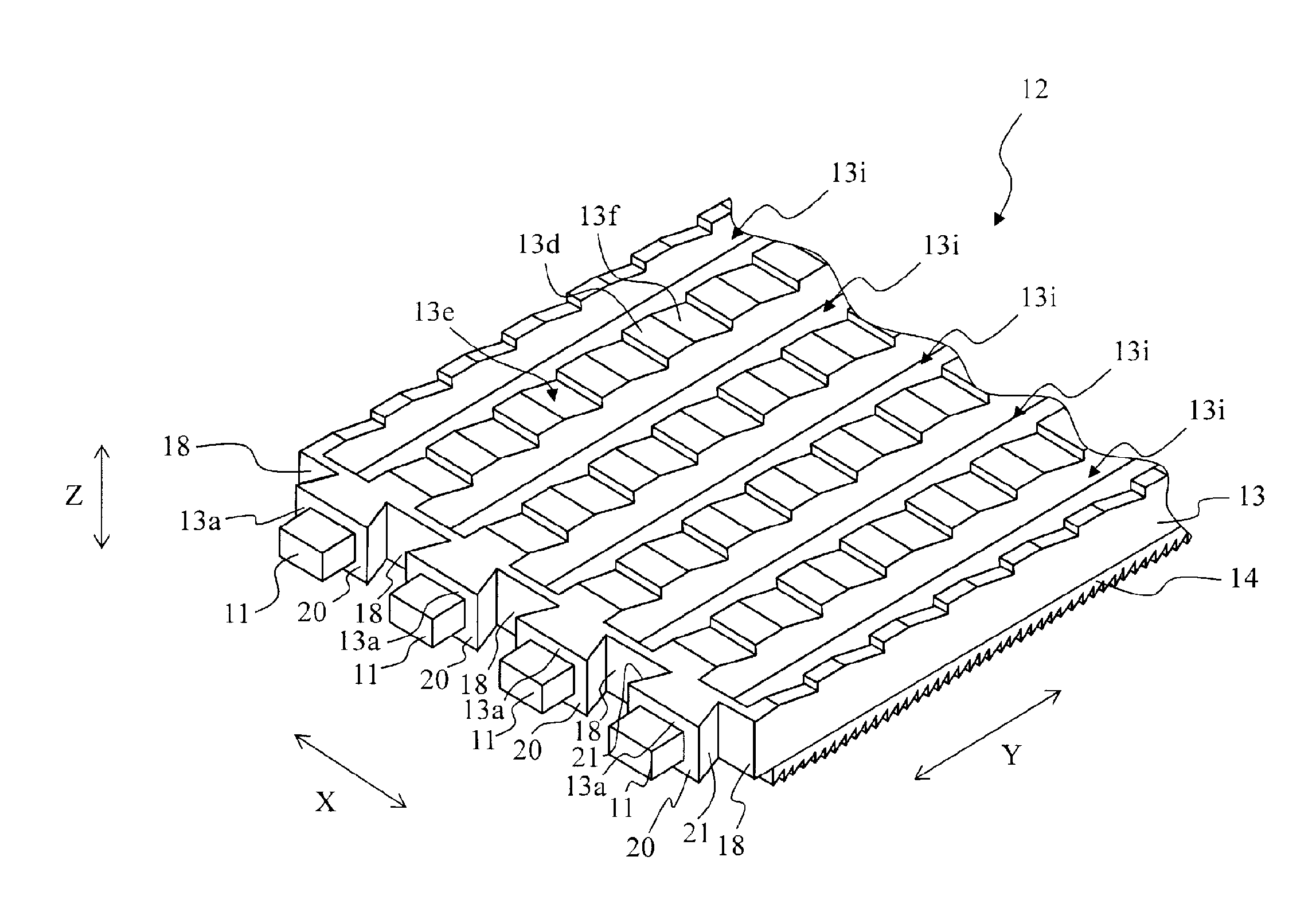
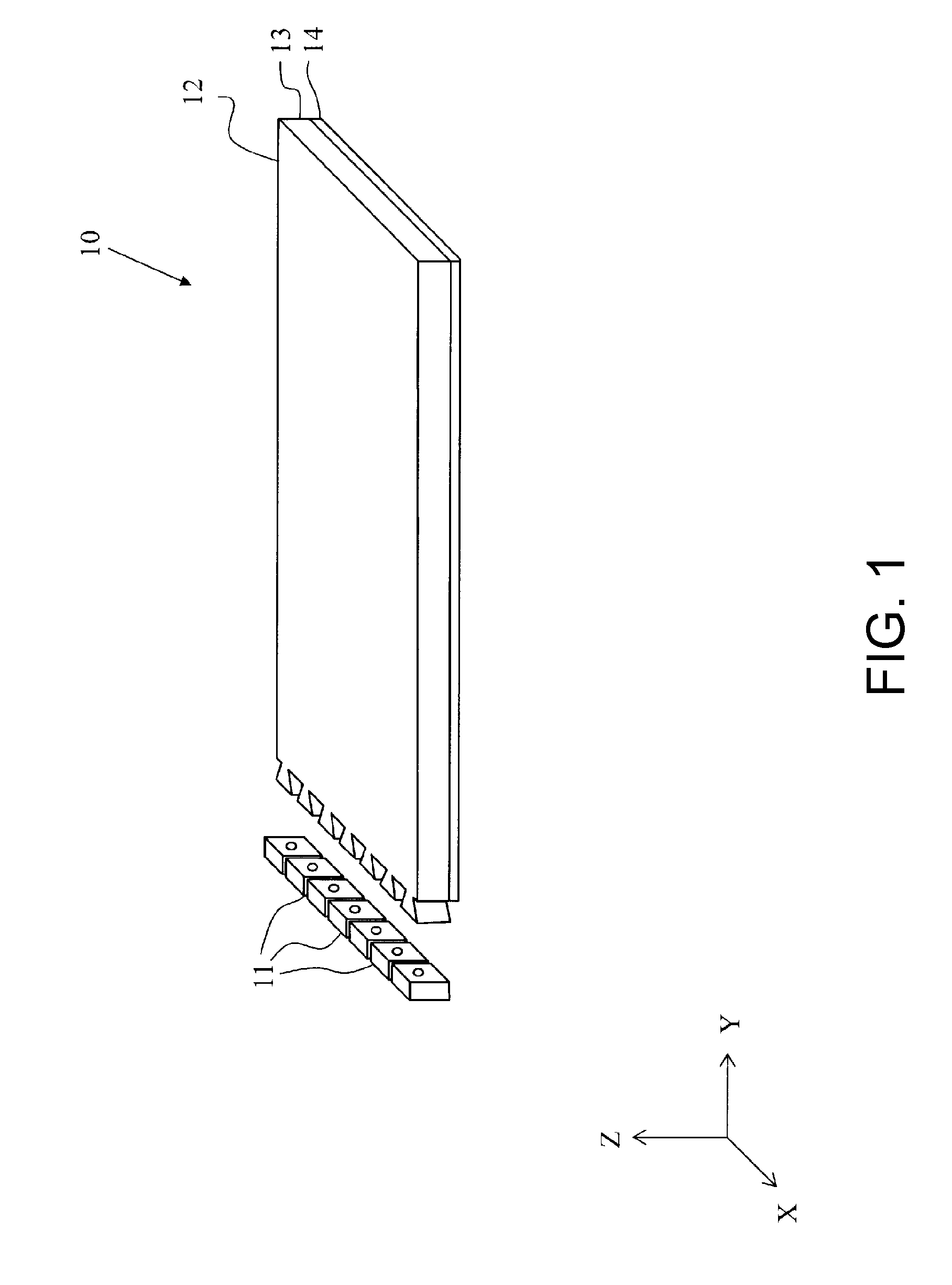
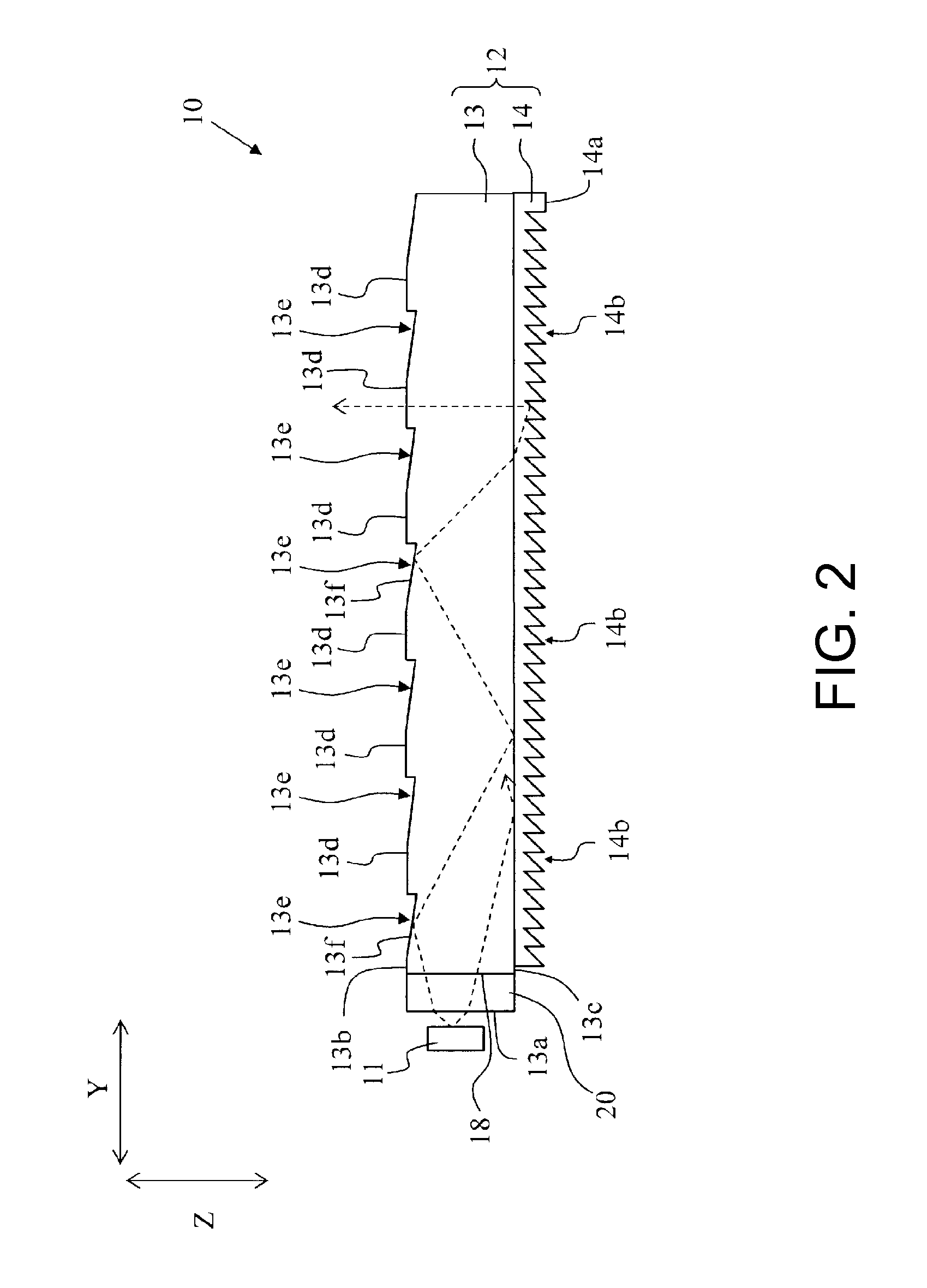
[0053]FIG. 1 is a schematic perspective view of one example of a backlight unit, which is an illumination device, according to the present invention. FIG. 2 is a side view of the backlight unit in FIG. 1. FIG. 3 is a schematic perspective view of a light guide plate used in the backlight unit shown in FIG. 2. FIG. 4 is a cross-sectional view in which the light exiting section of the light guide plate shown in FIG. 3 has been enlarged. FIG. 5 is a cross-sectional view of the light guide plate shown in FIG. 3. FIG. 6 is a cross-sectional view in which the rear side of the light guide plate shown in FIG. 3 has been enlarged. First, the shape of the backlight unit of the present invention will be explained. Hereinafter, the width direction of the backlight unit will be described as the X direction, the lengthwise direction as the Y direction, and the thickness direction as the Z direction.
[0054]A backlight unit 10 is an edge-lit backlight unit. As shown in FIGS. 1 and 2, this backlight ...
embodiment 2
[0106]Another example of an illumination device according to the present invention will be explained below with reference to the drawings. FIG. 15 is a side face view of one example of the light guide plate used in the backlight unit (illumination device) of the present invention. A backlight unit 10B shown in FIG. 15 has the same configuration as the backlight unit 10 except in regards to a low refractive index layer 140 and a prism layer 15, and the same reference characters are given to parts that are substantially the same, and a detailed explanation of these same parts will not be repeated.
[0107]As shown in FIG. 15, a light guide plate 12b of the backlight unit 10B includes a light guide body 13, the low refractive index layer 140, and the prism layer 15. Specifically, the low refractive index layer 140 is attached to the rear surface of the light guide body 13, and the prism layer 15 is attached to the surface of the low refractive index layer 140 opposite to the light guide b...
embodiment 3
[0113]Another example of an illumination device according to the present invention will be explained below with reference to the drawings. FIG. 16 is a front view of another example of the backlight unit (illumination device) of the present invention, and FIG. 17 is a side view of the backlight unit shown in FIG. 16. A backlight unit 10C shown in FIGS. 16 and 17 has the same configuration as the backlight unit 10 except for having a reflective member 16. In the explanation below, the same reference characters are given to parts that are substantially the same as the backlight unit 10, and a detailed explanation of the same parts will not be repeated. Furthermore, in FIG. 16, hatching has been used to help show the reflective member 16 for clarity of explanation.
[0114]Light that is emitted from LEDs 11 and enters a light guide body 13 appears as V-shaped bright lines at spread angles of approximately ±39° from an optical axis, as described above. In this range, light that is emitted ...
PUM
 Abstract
Description
Claims
Application Information
 - R&D
- Intellectual Property
- Life Sciences
- Materials
- Tech Scout
- Unparalleled Data Quality
- Higher Quality Content
- 60% Fewer Hallucinations
Browse by: Latest US Patents, China's latest patents, Technical Efficacy Thesaurus, Application Domain, Technology Topic, Popular Technical Reports.
© 2025 PatSnap. All rights reserved.Legal|Privacy policy|Modern Slavery Act Transparency Statement|Sitemap|About US| Contact US: help@patsnap.com


