Screws for generating and applying compression within a body

a technology of compression screw and body, applied in the field of surgical screw, can solve the problems of slow healing process, device failure to achieve the goal of achieving the effect of compression, and disrupting the healing tissu

Active Publication Date: 2015-05-14
ARTHREX
View PDF1 Cites 12 Cited by
  • Summary
  • Abstract
  • Description
  • Claims
  • Application Information

AI Technical Summary

Benefits of technology

[0029]said compression screw interface of said cannulated inner driver being sized such that, when said shaft of said compression screw is stretched, and when said compression screw is mounted on said compression screw interface such that said interface shaft is inserted into said lumen of said compression screw such that said proximal screw thread of said compression screw is disposed adjacent to said proximal screw thread of said compression screw interface, said interface drive feature of said compression screw interface engages said drive feature of said compression screw and said distal end surface of said interface shaft engages said first shoulder of said compression screw, whereby to prevent foreshortening of said stretched compression screw.

Problems solved by technology

Furthermore, gaps between bone fragments that are too large allow motion to occur between the bone fragments, disrupting the healing tissue and thus slowing the healing process.
While these devices are designed to bring the bone fragments into close contact and to generate a compressive load between the bone fragments, these devices do not always succeed in accomplishing this objective.
Among other things, the differential pitch on headless bone screws is able to reduce gaps and to initially create compressive loads; however, it is widely reported that the compressive load dissipates rapidly as the bone relaxes and remodels around the threads.
Furthermore, with headless bone screws comprising two separated threads, the gap reduction is limited by relatively small pitch differential and short thread length.

Method used


Image

  • Screws for generating and applying compression within a body
  • Screws for generating and applying compression within a body
  • Screws for generating and applying compression within a body

Examples


Embodiment Construction

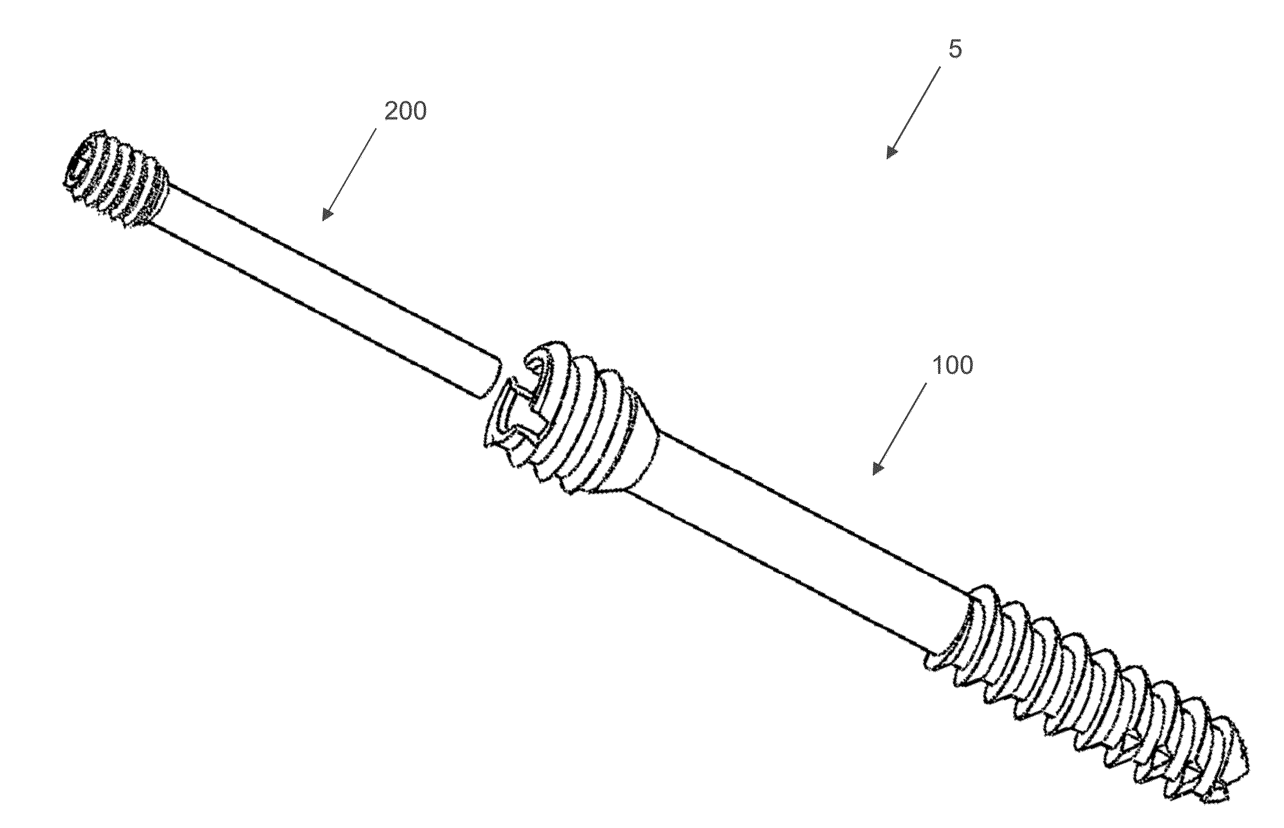
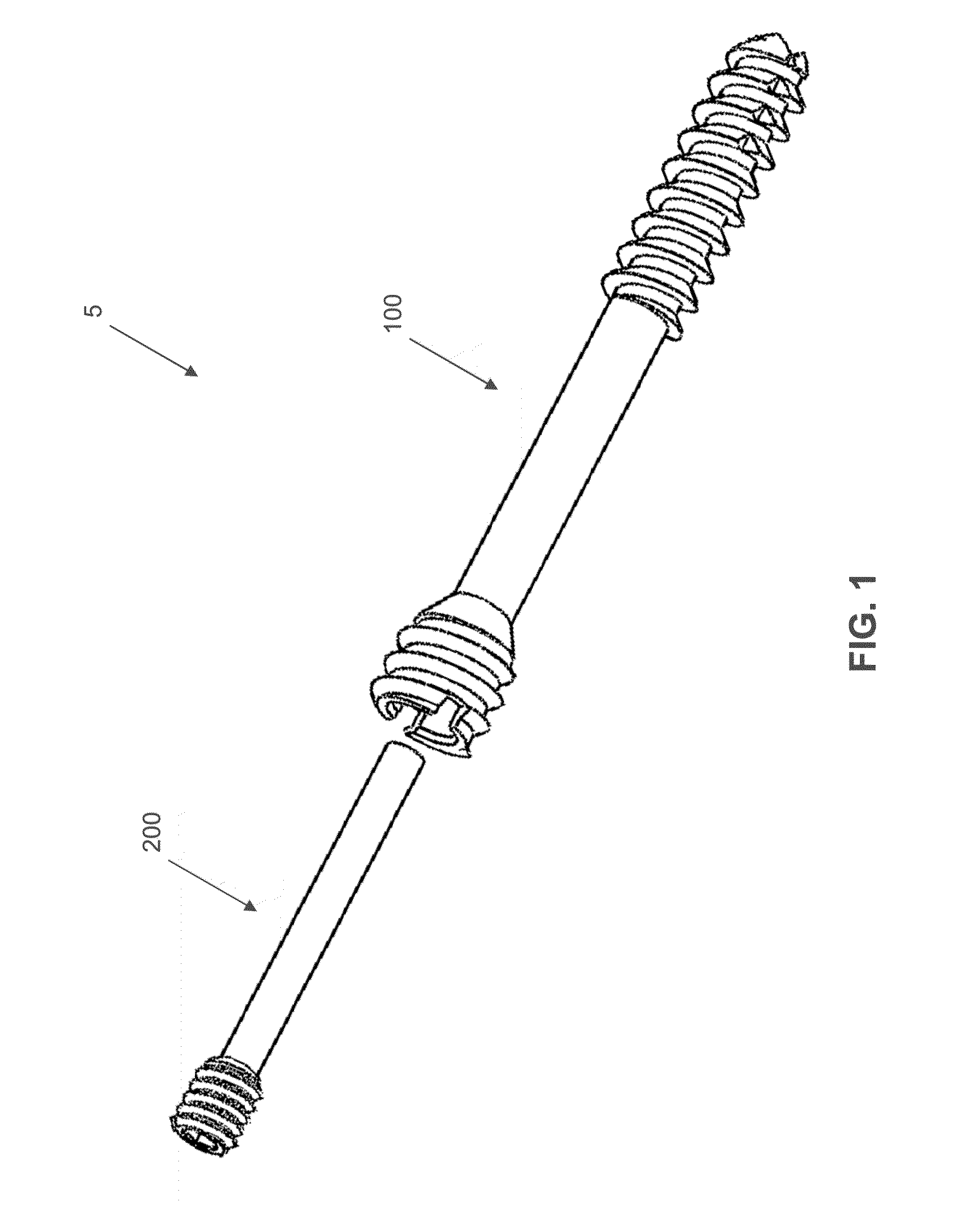
[0045]Looking first at FIG. 1, there is shown a novel compression screw system 5 for bringing bone fragments into close proximity with each other, generating a compressive load, and maintaining that compressive load for a prolonged period of time while the bone tissue heals. Novel compression screw system 5 generally comprises a compression screw 100 and an internal retaining pin 200, as will hereinafter be discussed.

[0046]In one preferred form of the invention, compression screw 100 and internal retaining pin 200 are provided in the form of a sterilized kit. The kit may include additional instruments to aid in the implantation of the screw (e.g., k-wire, drill bit, screw size guide, etc.).

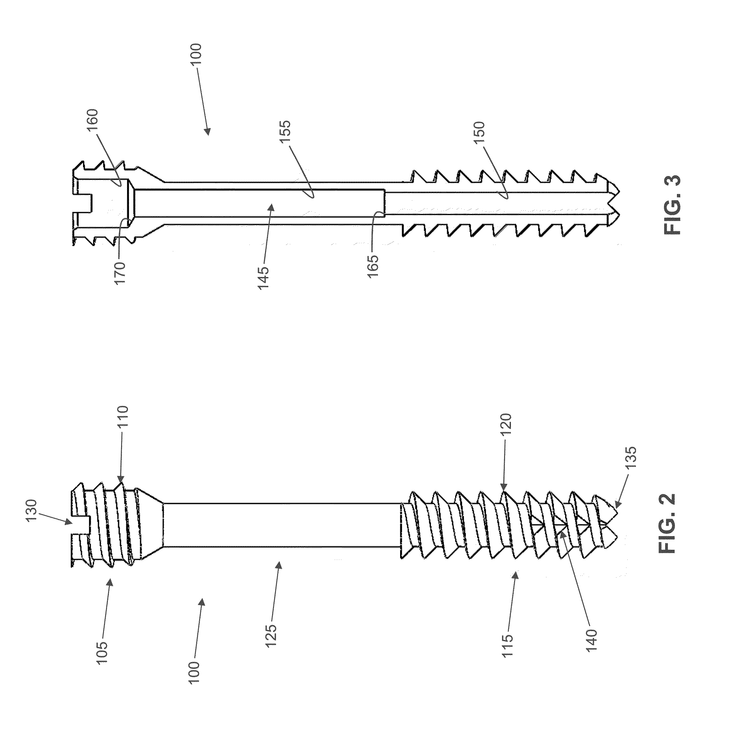
[0047]Compression screw 100 is shown in greater detail in FIGS. 2 and 3. Compression screw 100 is manufactured from a shape memory material (e.g., a material capable of exhibiting superelasticity and / or a temperature-induced shape change). The shape memory material may be a metal alloy (e.g., Niti...


PUM


Abstract

A compression screw system, said compression screw system comprising:
    • a compression screw comprising a shaft, a screw thread formed on said shaft at a distal location, and a bone-engaging feature formed on said shaft at a proximal location, wherein at least a portion of said shaft disposed between said screw thread and said bone-engaging feature is capable of being stretched; and
    • a holding element connectable to said compression screw for releasably holding said at least a portion of said shaft in a stretched condition.

Description

REFERENCE TO PENDING PRIOR PATENT APPLICATIONS[0001]This patent application:[0002](1) claims benefit of pending prior U.S. Provisional Patent Application Ser. No. 61 / 902,338, filed Nov. 11, 2013 by MX Orthopedics, Corp. and Matthew Palmer et al. for SUPERELASTIC AND SHAPE MEMORY CANNULATED INTERFRAGMENTARY BONE COMPRESSION SCREW (Attorney's Docket No. FONTE-32 PROV); and[0003](2) claims benefit of pending prior U.S. Provisional Patent Application Ser. No. 61 / 903,820, filed Nov. 13, 2013 by MX Orthopedics, Corp. and Matthew Palmer et al. for BONE STAPLES, INTRAMEDULLARY FIXATION DEVICES, SOFT TISSUE ANCHORS AND PINS SCREWS CAN BE SHORTENED IN VIVO TO IMPROVE FRACTURE REDUCTION BY USING SUPERELASTIC OR SHAPE MEMORY EFFECT CHARACTERISTICS OF NITINOL (Attorney's Docket No. FONTE-34 PROV).[0004]The two (2) above-identified patent applications are hereby incorporated herein by reference.FIELD OF THE INVENTION[0005]The present invention relates to screws for generating and applying compres...

Claims


Application Information

Patent Timeline
Patent Type & Authority Applications(United States)
IPC IPC(8): A61B17/86
CPCA61B17/863A61B17/864A61B17/8685A61B17/8894A61B17/8875
Inventor PALMER, MATTHEWDEVANEY, ROBERTEL KHAJA, RAGHEBSENNETT, ANDREWFONTE, MATTHEW
Owner ARTHREX
Why Eureka
Try Eureka