Charged Particle Beam Instrument

a particle beam and instrument technology, applied in instruments, heat measurement, machines/engines, etc., can solve the problems of affecting the operation of the instrument. , to achieve the effect of easy in-situ observation

Active Publication Date: 2015-05-21
JEOL LTD
View PDF4 Cites 4 Cited by
  • Summary
  • Abstract
  • Description
  • Claims
  • Application Information

AI Technical Summary

Benefits of technology

[0010]In view of these problems, the present invention has been made. One object associated with some aspects of the present in

Problems solved by technology

In the aforementioned technique using a diaphragm holder, it takes a great deal of time to fabricate a diaphragm permitting passage of an electron beam.
Furthermore, there is the possibility that the fabricated diaphragm may break suddenly.
This creates the danger that the electron micros

Method used


Image

  • Charged Particle Beam Instrument
  • Charged Particle Beam Instrument
  • Charged Particle Beam Instrument

Examples


Embodiment Construction

[0047]The preferred embodiments of the present invention are hereinafter described in detail with reference to the drawings. It is to be understood that the embodiments provided below do not unduly restrict the scope of the present invention delineated by the appended claims and that not all the configurations described below are essential constituent components of the invention.

1. Charged Particle Beam Instrument

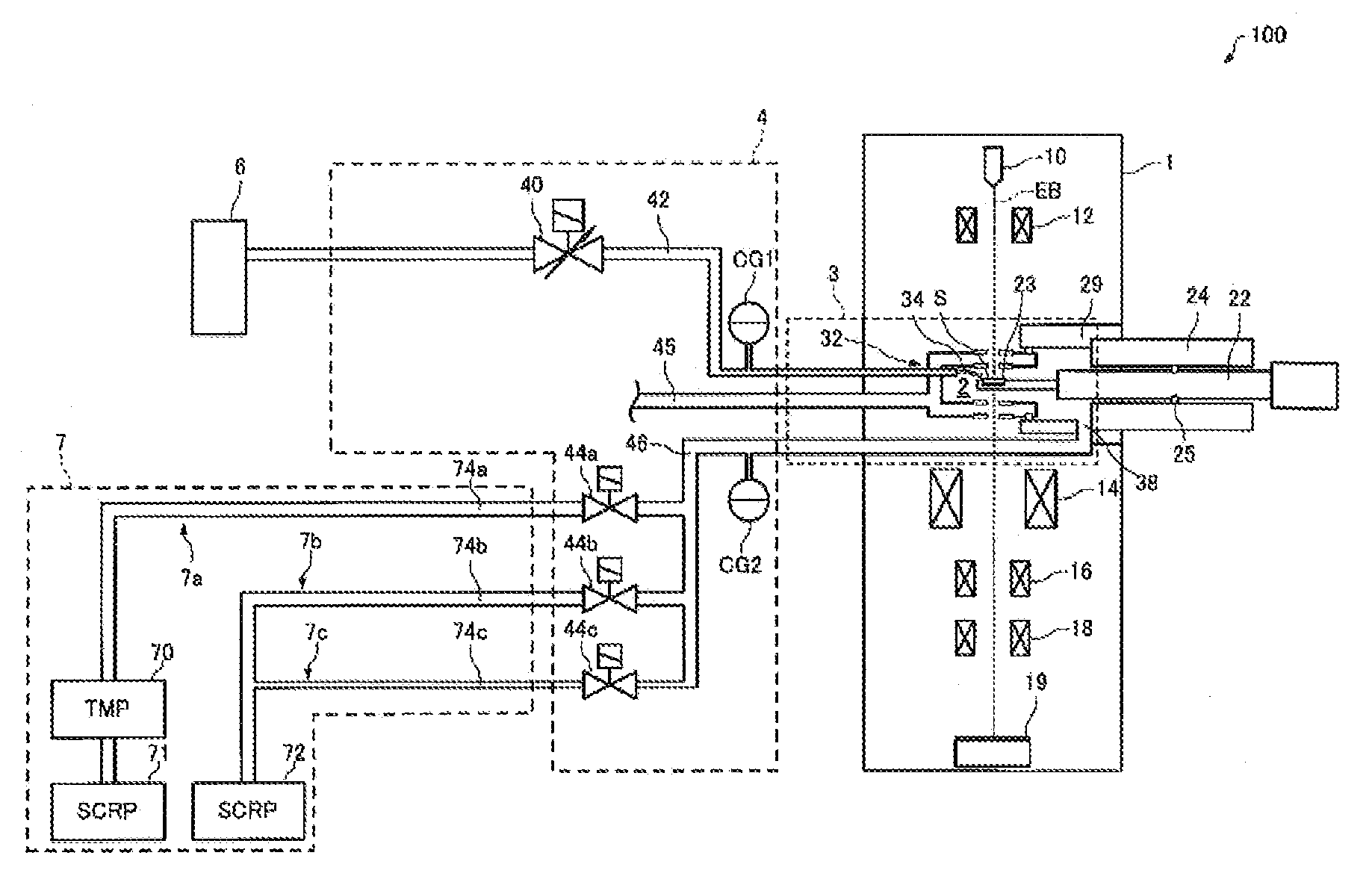
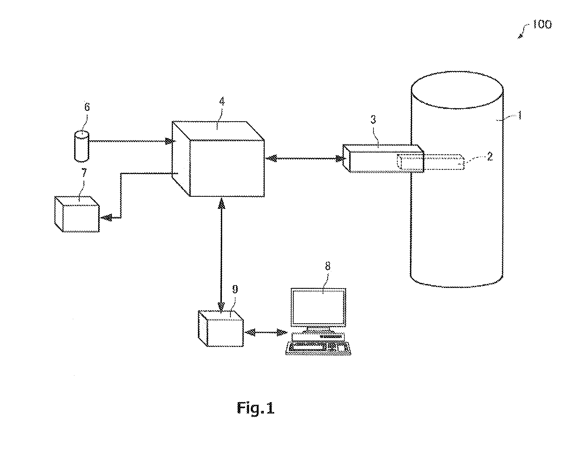
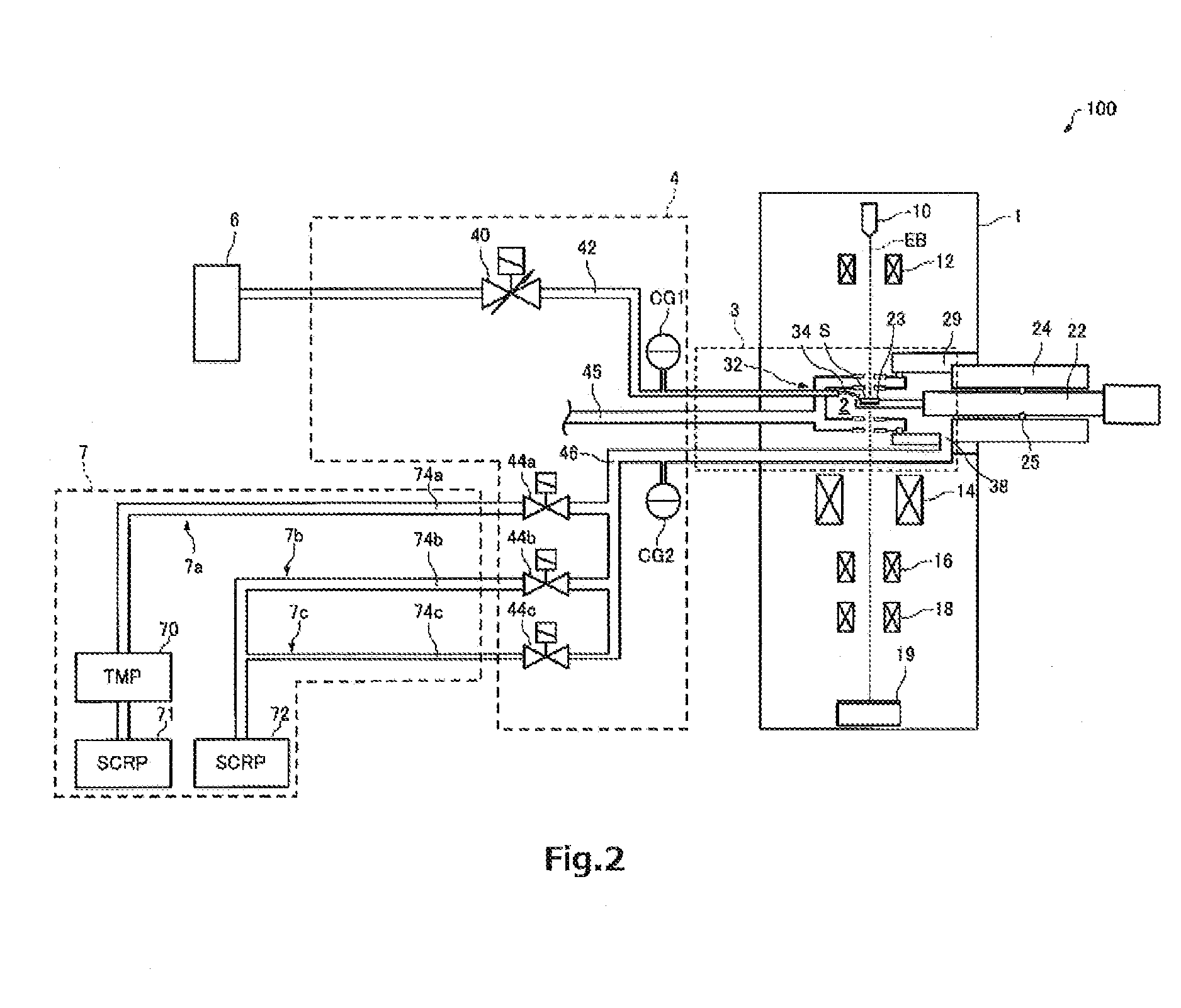
[0048]The configuration of a charged particle beam instrument associated with one embodiment of the present invention is described by referring to FIG. 1, which shows the configuration of the charged particle beam instrument, generally indicated by reference numeral 100. It is herein assumed that the charged particle beam instrument 100 is a transmission electron microscope (TEM).

[0049]As shown in FIG. 1, the charged particle beam instrument 100 is configured including a body 1 constituting an electron optical column, a gas inlet mechanism 3, a gaseous environment adjuster ...


PUM


Abstract

A charged particle beam instrument is offered which can easily perform an in situ observation in a gaseous atmosphere. The charged particle beam instrument (100) is used to perform an observation of a specimen (S) placed in a gaseous atmosphere and has a specimen chamber (2), a gas supply portion (6) for supplying a gas into the specimen chamber (2), a venting portion (7) for venting the specimen chamber (2), a gaseous environment adjuster (4), and a gas controller (812) for controlling the gaseous environment adjuster (4). This adjuster (4) has a gas inflow rate adjusting valve (40) for adjusting the flow rate of the gas supplied into the specimen chamber (2) and a first vacuum gauge (CG1) for measuring the pressure of the gas supplied into the specimen chamber (2). The gas controller (812) sets a target value of pressure for the gas supplied into the specimen chamber (2) based on a predetermined relational expression indicating a relationship between the reading of the first vacuum gauge (CG1) and the pressure inside the specimen chamber (2) and on a corrective coefficient for correcting the reading of the first vacuum gauge (CG1) according to the species of the gas supplied into the specimen chamber (2) and controls the gas inflow rate adjusting valve (40) such that the reading of the first vacuum gauge (CG1) reaches the target value of pressure.

Description

BACKGROUND OF THE INVENTION[0001]1. Field of the Invention[0002]The present invention relates to a charged particle beam instrument.[0003]2. Description of Related Art[0004]Known techniques for performing in situ observations in a gaseous atmosphere by a charged particle beam instrument such as an electron microscope use a diaphragm holder or a differential pumping system.[0005]The former technique using the diaphragm holder makes use of a specimen holder having a space. A diaphragm through which an electron beam can be transmitted is used in this space. This space is filled with a gas. Under this condition, a specimen is observed.[0006]On the other hand, in the latter technique using the differential pumping system, a gas, is directly introduced into a specimen chamber within an electron optical column. An in situ observation is performed while differentially pumping a space partitioned by plates to prevent leakage of gas to surroundings, the plates being provided with orifices to ...

Claims


Application Information

Patent Timeline
IPC IPC(8): H01J37/18H01J37/20H01J41/02
CPCH01J37/18H01J37/20H01J2237/2002H01J2237/182H01J2237/2605H01J41/02
Inventor HIROKI, YASUSHIOHSAKI, MITSUAKI
Owner JEOL LTD
Why Eureka
Try Eureka