
Metrology Method and Apparatus, Substrate, Lithographic System and Device Manufacturing Method

Active Publication Date: 2015-05-21
ASML NETHERLANDS BV
View PDF3 Cites 52 Cited by
  • Summary
  • Abstract
  • Description
  • Claims
  • Application Information

AI Technical Summary

Benefits of technology

The patent text describes a technique for improving accuracy in measuring metrology in composite target structures by using small gratings. The technique aims to avoid the drawbacks associated with selecting smaller targets in order to maintain the benefits of using small gratings. The technical effect is to improve accuracy over prior published techniques while avoiding the limitations of selecting smaller targets.

Problems solved by technology

Consequently the measurements are inherently more noisy, for a given acquisition time.
Moreover, any variation in positioning the ROI becomes a significant source of error in the measured asymmetry.

Method used


Image

  • Metrology Method and Apparatus, Substrate, Lithographic System and Device Manufacturing Method
  • Metrology Method and Apparatus, Substrate, Lithographic System and Device Manufacturing Method
  • Metrology Method and Apparatus, Substrate, Lithographic System and Device Manufacturing Method

Examples


Embodiment Construction

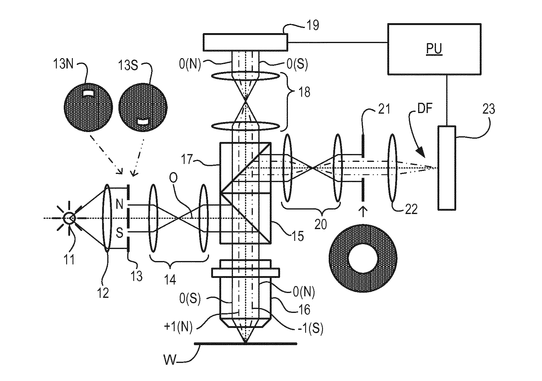
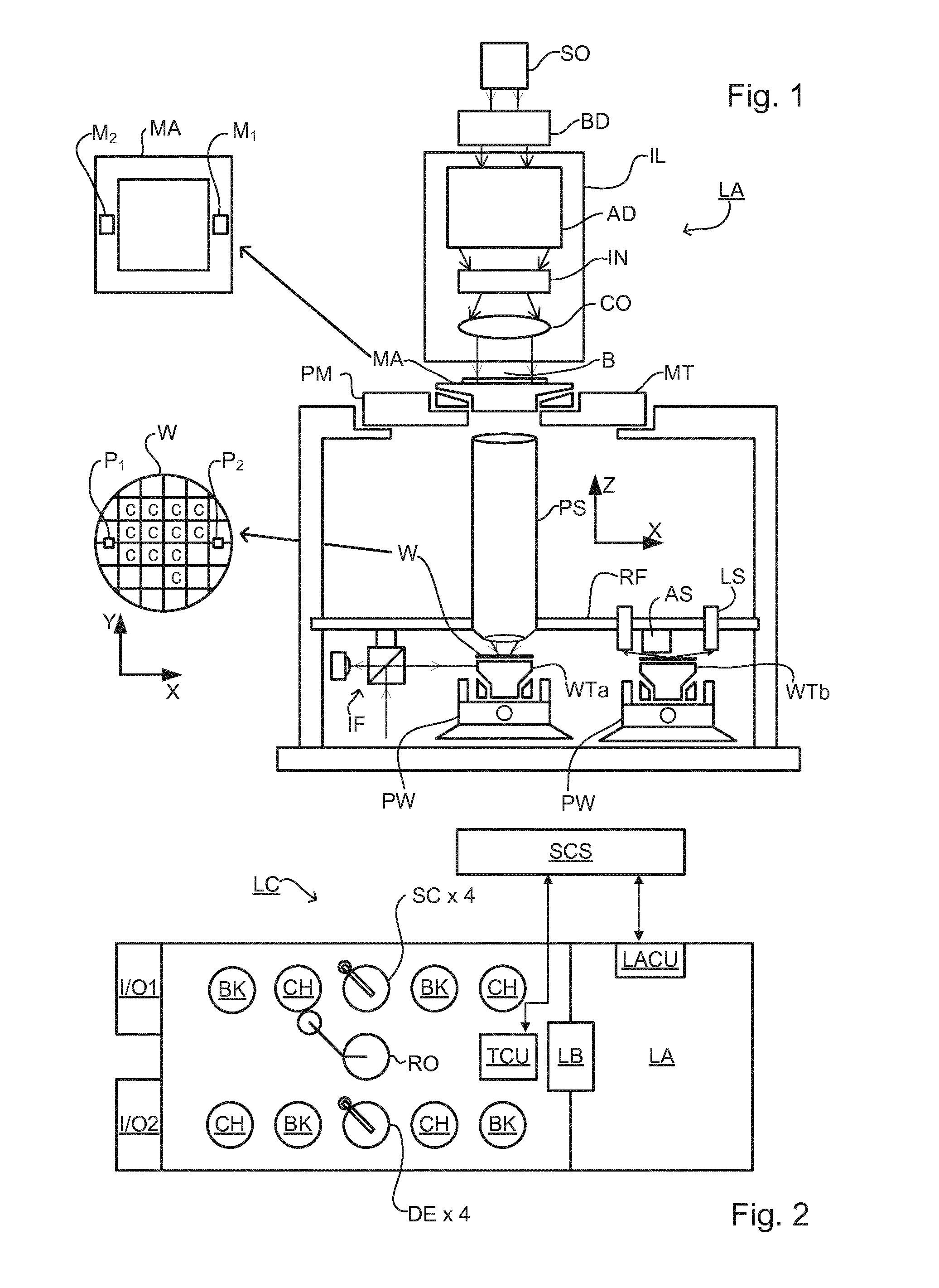
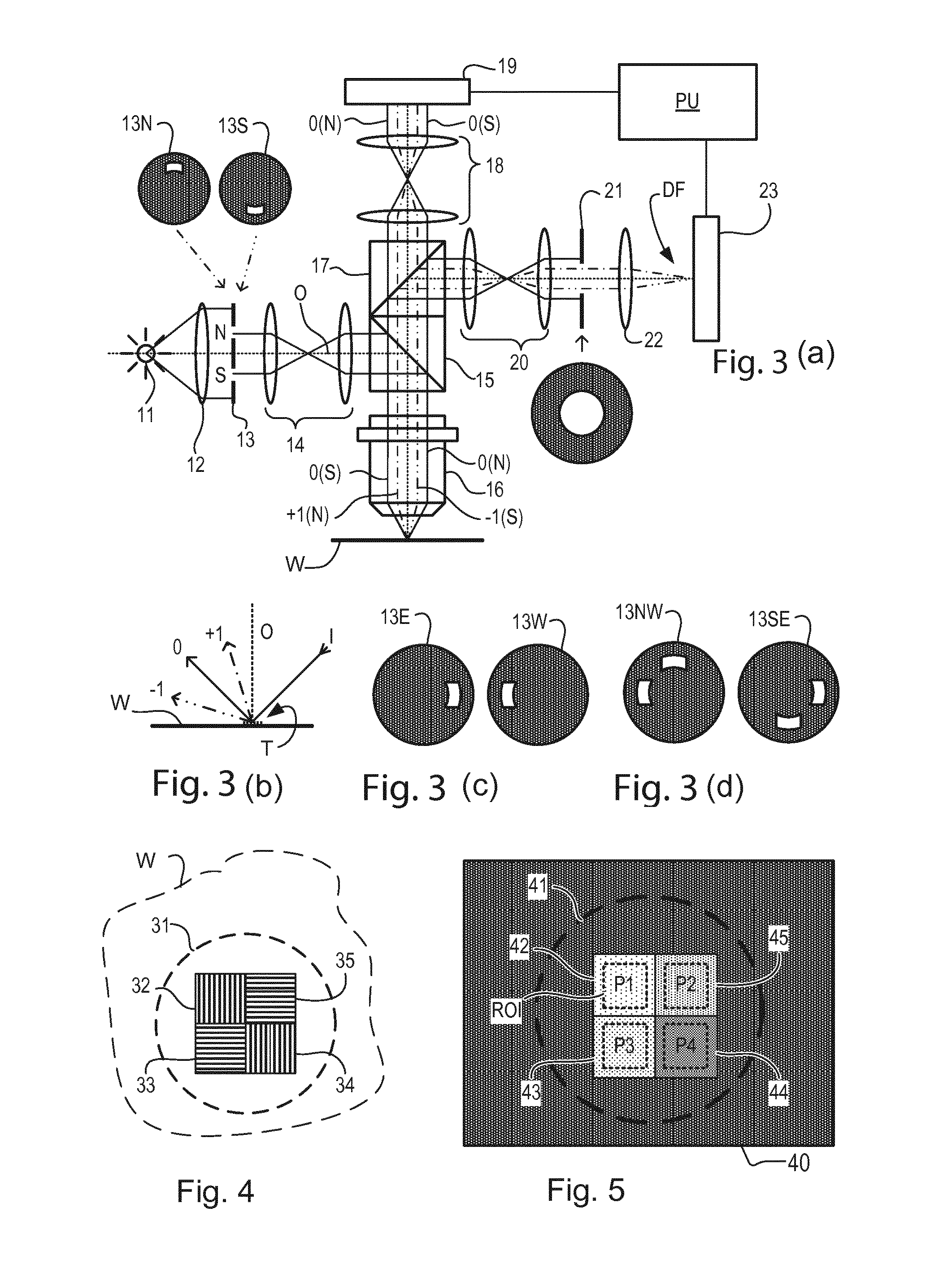
[0034]This specification discloses one or more embodiments that incorporate the features of this invention. The disclosed embodiment(s) merely exemplify the invention. The scope of the invention is not limited to the disclosed embodiment(s). The invention is defined by the claims appended hereto.

[0035]The embodiment(s) described, and references in the specification to “one embodiment”, “an embodiment”, “an example embodiment”, etc., indicate that the embodiment(s) described may include a particular feature, structure, or characteristic, but every embodiment may not necessarily include the particular feature, structure, or characteristic. Moreover, such phrases are not necessarily referring to the same embodiment. Further, when a particular feature, structure, or characteristic is described in connection with an embodiment, it is understood that it is within the knowledge of one skilled in the art to effect such feature, structure, or characteristic in connection with other embodimen...


PUM


Abstract

A metrology target formed by a lithographic process on a substrate includes a plurality of component gratings. Images of the target are formed using +1 and −1 orders of radiation diffracted by the component gratings. Regions of interest (ROIs) in the detected image are identified corresponding the component gratings. Intensity values within each ROI are processed and compared between images, to obtain a measurement of asymmetry and hence overlay error. Separation zones are formed between the component gratings and design so as to provide dark regions in the image. In an embodiment, the ROIs are selected with their boundaries falling within the image regions corresponding to the separation zones. By this measure, the asymmetry measurement is made more tolerant of variations in the position of the ROI. The dark regions also assist in recognition of the target in the images.

Description

CROSS-REFERENCE TO RELATED APPLICATIONS[0001]This application claims the benefit of U.S. provisional application 61 / 652,552, which was filed on May 29, 2012 and which is incorporated herein in its entirety by reference.BACKGROUND[0002]1. Field of the Present invention[0003]The present invention relates to methods and apparatus for metrology usable, for example, in the manufacture of devices by lithographic techniques and to methods of manufacturing devices using lithographic techniques.[0004]2. Background Art[0005]A lithographic apparatus is a machine that applies a desired pattern onto a substrate, usually onto a target portion of the substrate. A lithographic apparatus can be used, for example, in the manufacture of integrated circuits (ICs). In that instance, a patterning device, which is alternatively referred to as a mask or a reticle, may be used to generate a circuit pattern to be formed on an individual layer of the IC. This pattern can be transferred onto a target portion (...

Claims


Application Information

Patent Timeline
IPC IPC(8): G03F7/20
CPCG03F7/70483G03F7/70633G03F7/70683G03F7/70625H01L21/0274H01L22/12
Inventor JAK, MARTIN JACOBUS JOHANKOOLEN, ARMAND EUGENE ALBERTSMILDE, HENDRIK JAN HIDDE
Owner ASML NETHERLANDS BV
Features
  • Generate Ideas
  • Intellectual Property
  • Life Sciences
  • Materials
  • Tech Scout
  • Unparalleled Data Quality
  • Higher Quality Content
  • 60% Fewer Hallucinations
Learn More