
Hybrid foundation structure, and method for building same

a foundation structure and hybrid technology, applied in the field of foundation structure, can solve the problems of overloaded boring equipment, unefficient, and conventional piles, and achieve the effects of high bearing capacity, cost-effectiveness, and fast solidification

Active Publication Date: 2015-05-21
EXT
View PDF18 Cites 11 Cited by
  • Summary
  • Abstract
  • Description
  • Claims
  • Application Information

AI Technical Summary

Benefits of technology

The present invention provides a foundation structure that can securely support heavy loads and prevent soil subsidence by using various support layers based on the depth of the ground. Additionally, using solidified soil or field generated soil can lead to quick solidification, and this method is cost-effective. Finally, creating a small hole in the deep depth can reduce the amount of materials needed and prevent overload of equipment.

Problems solved by technology

First, the ground is not formed to have a generally constant bearing capacity of soil and there exist layers (supporting layers such as a weak stratum, a rock layer, and so on) having different bearing capacities of soil from each other according to their depths. Despite this, conventional piles have all the same cross sections regardless of the depth, and therefore are not efficient.
Second, because a boring hole should be formed with the same diameter even in the deep depth, boring equipment is overloaded.

Method used


Image

  • Hybrid foundation structure, and method for building same
  • Hybrid foundation structure, and method for building same
  • Hybrid foundation structure, and method for building same

Examples


Embodiment Construction

[0042]1: boring hole[0043]10: upper support layer[0044]11: variable cross-section support layer[0045]12: large boring hole[0046]20: lower support layer[0047]21: core[0048]22: small boring hole[0049]a, a1, a2: weak stratum[0050]b, b1, b2: support layer

BEST MODE

[0051]Hereunder is given a more detailed description of exemplary embodiments according to the present invention using appended drawings.

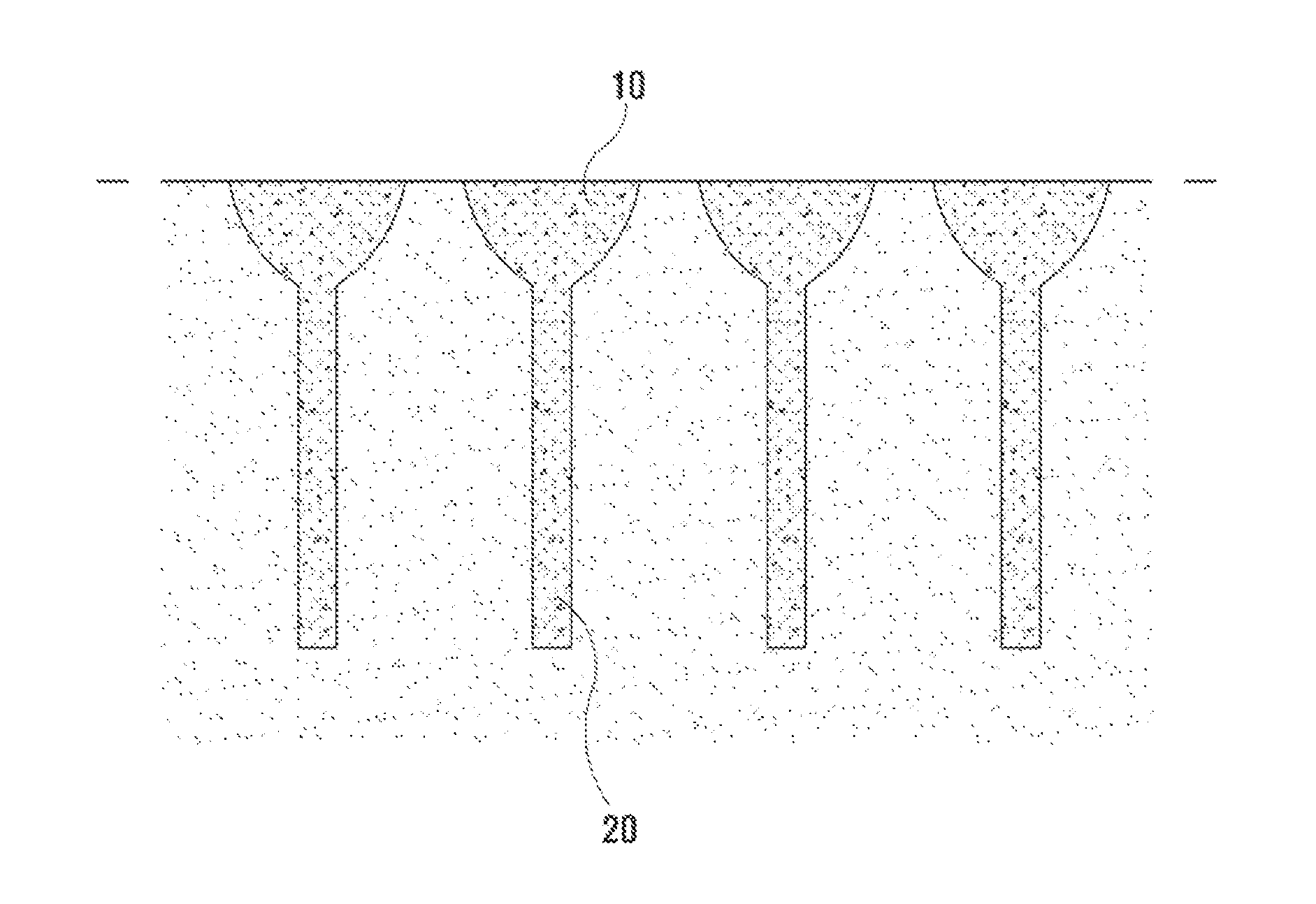
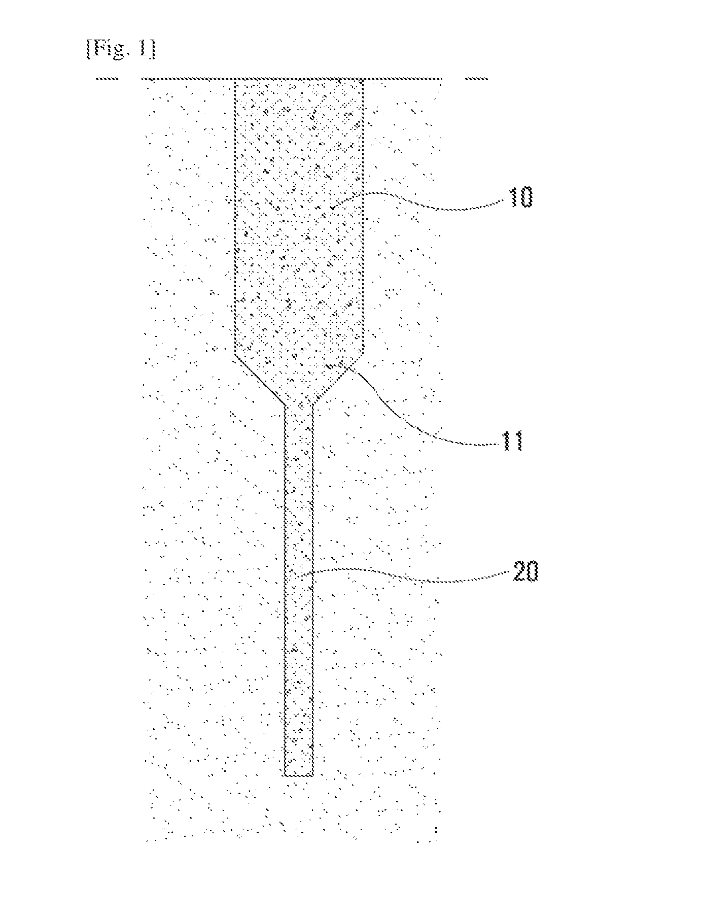
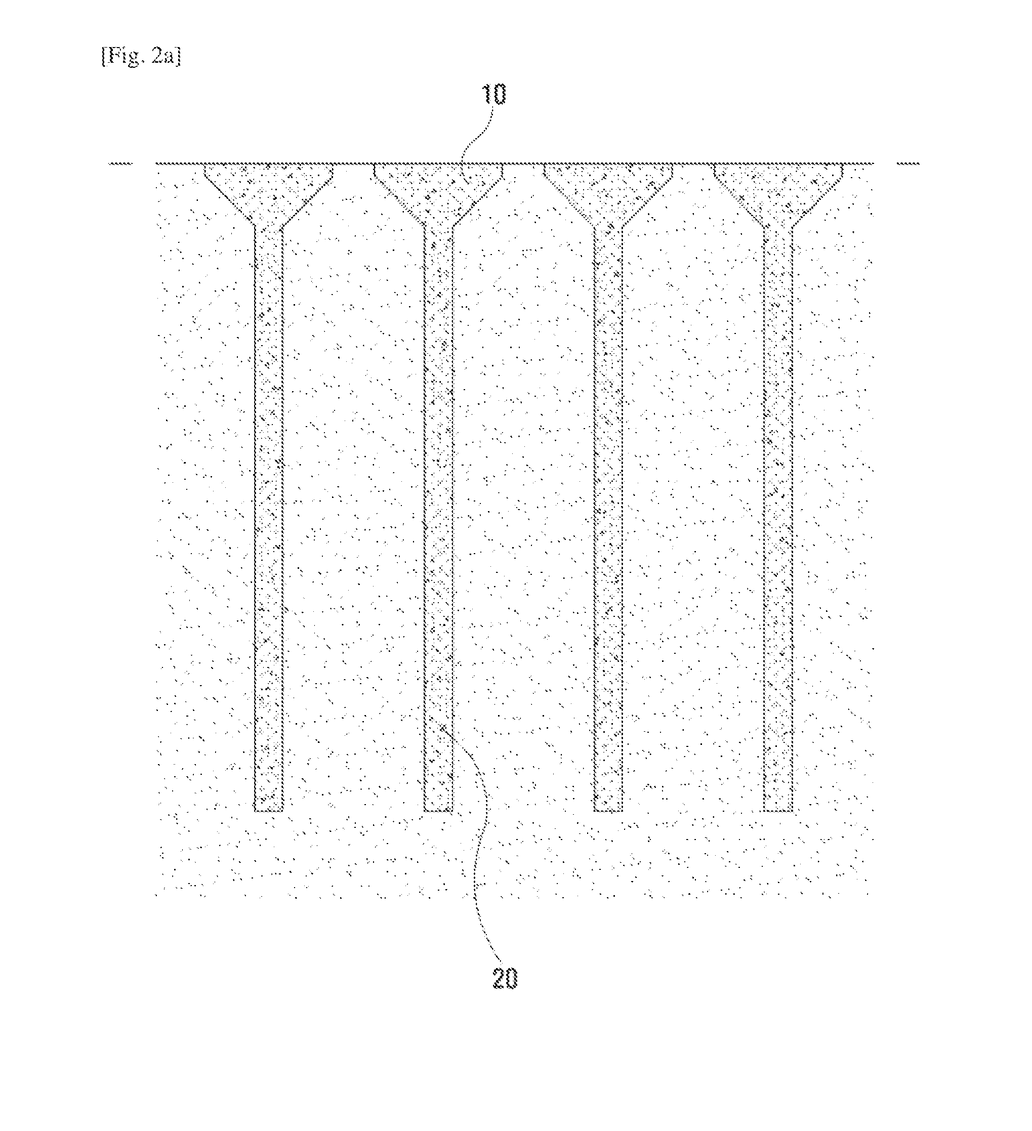
[0052]As illustrated in FIG. 1 and the rest, the present invention relates to a foundation structure vertically installed on the ground, and comprising: an upper support layer 10 formed on the ground in the vertical direction; a lower support layer 20 extended downward from the upper support layer 10 in order to have the narrower width compared to the width of the upper support layer 10.

[0053]And the upper support layer 10 and the lower support layer 20 are formed by the injection of solidified soil which is the mixture of earth, sand, and a soil-solidifying agent.

[0054]That is, the present di...


PUM


Abstract

The present invention relates to a foundation structure vertically installed on the ground, and comprising: an upper support layer 10 formed on the ground in the vertical direction; and a lower support layer 20 formed so as to extend downward from the upper support layer 10 and such that the width thereof is less than that of the upper support layer 10. The disclosed upper support layer 10 and the lower support layer 20 are structures formed from soil solidified by means of feeding and mixing an earth and soil-solidifying agent therein, and therefore are efficient and prevent overload due to boring equipment.

Description

TECHNICAL FIELD[0001]The present invention relates to the civil engineering field, more particularly, a foundation structure.BACKGROUND ART[0002]In order to ensure the ground's bearing capacity of soil for constructing a structure, linear piles including steel piles, PHC piles, etc. are generally constructed.[0003]However, these conventional piles have the following problems.[0004]First, the ground is not formed to have a generally constant bearing capacity of soil and there exist layers (supporting layers such as a weak stratum, a rock layer, and so on) having different bearing capacities of soil from each other according to their depths. Despite this, conventional piles have all the same cross sections regardless of the depth, and therefore are not efficient.[0005]Second, because a boring hole should be formed with the same diameter even in the deep depth, boring equipment is overloaded.DISCLOSURETechnical Problem[0006]The present invention is devised to solve problems described a...

Claims


Application Information

Patent Timeline
Patent Type & Authority Applications(United States)
IPC IPC(8): E02D3/12E02D27/16E02D27/32E02D17/02
CPCE02D3/12E02D27/32E02D27/16E02D17/02E02D3/08E02D5/48E02D5/28E02D5/30E02D5/36E02D2250/0023E02D2250/003E02D2300/002E02D2300/0029
Inventor SONG, KI YONG
Owner EXT
Learn More