
Structure of body side weather strip

a technology of weather strip and body, which is applied in the direction of vehicle sealing arrangement, mechanical equipment, transportation and packaging, etc., can solve the problems of body side weather strip damage, tube wear, protective coating layer damage, etc., and achieves the effect of minimizing deformation, satisfactory friction standard, and minimizing stress in the tub

Inactive Publication Date: 2015-05-28
HYUNDAI MOTOR CO LTD +1
View PDF34 Cites 4 Cited by
  • Summary
  • Abstract
  • Description
  • Claims
  • Application Information

AI Technical Summary

Benefits of technology

The present invention provides a structure for a body side weather strip that prevents excessive deformation of the tube due to the hip of a passenger getting into a vehicle. This is achieved by incorporating a two-stage folding structure including a first folding portion and / or a second folding portion. The structure also minimizes deformation of the body side weather strip by providing a step or gap between the end of the first folding portion and the side of the carrier, which prevents contact between the body side weather strip and the passenger's hip. The technical effect of this invention is to provide a safer and more comfortable vehicle interior.

Problems solved by technology

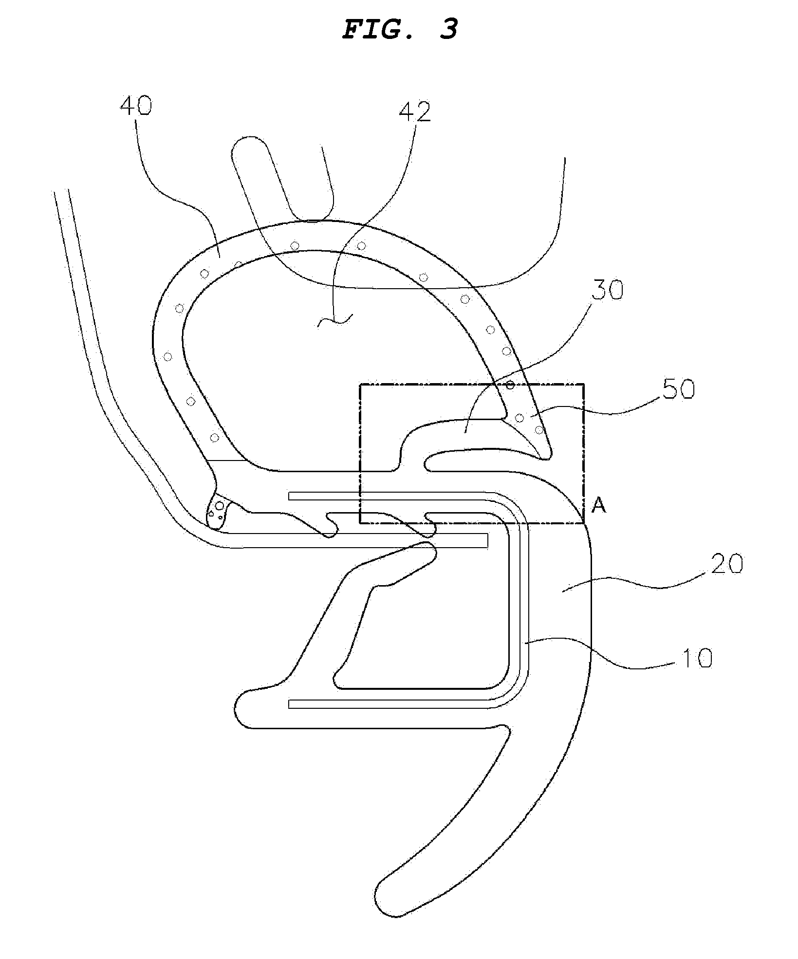
However, the structure of the body side weather strip of the related art has a problem in that the tube of the body side weather strip is too much deformed by the hip of a passenger getting into / out of the vehicle and accordingly, the body side weather strip is damaged, for example, cracks on the surface of the tube or breakage of the protective coating layer over the tensile strength of the tube.
The surface of the tube is scratched by friction between the tube surface and the hip of a passenger getting into / out of the vehicle or between the tube and the carrier, such that the protective coating layer of the tube is damaged and the tube is worn.
In particular, for heavy passengers, at the backseats with relatively small door openings of a vehicle body, and in taxes that passengers frequently get in / off, the body weather strips are frequently damaged.
According to an abrasion resistance test in which a friction member is rubbed at 45° against a cross-section of a body side weather strop in consideration of the actual field conditions, there is a problem in that the body side weather strips of the related art fail to satisfy the friction standard (e.g., no damage under 2,000 times).

Method used


Image

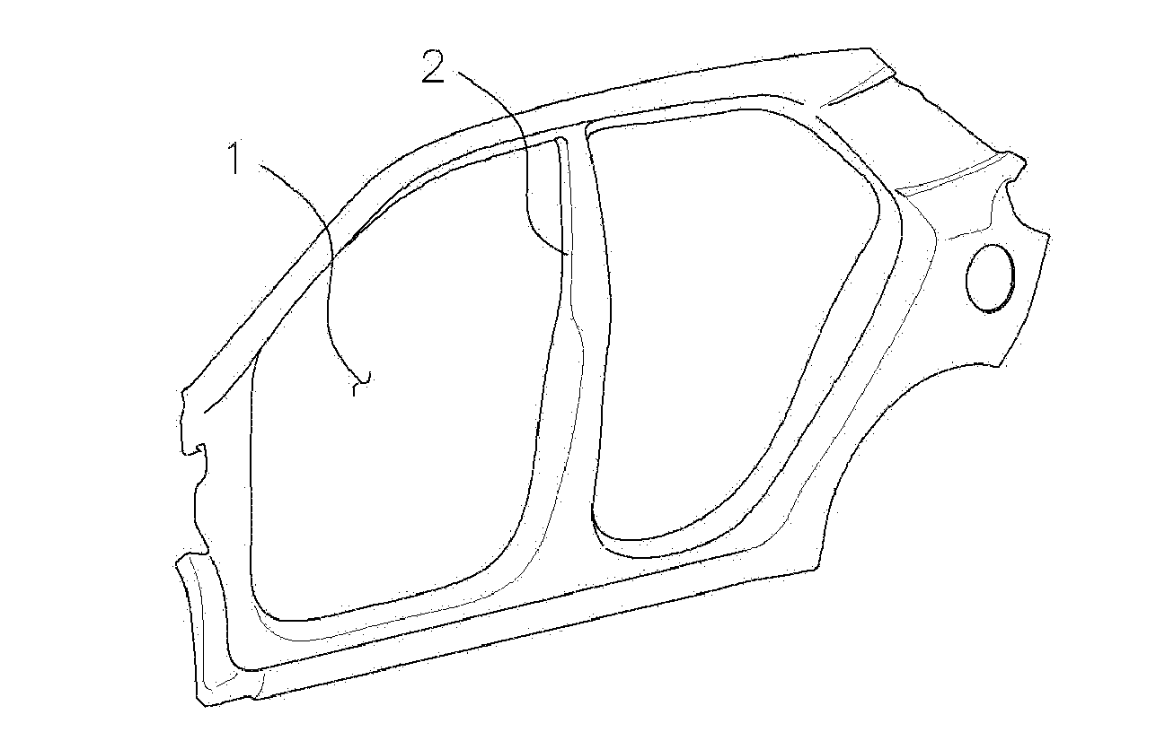
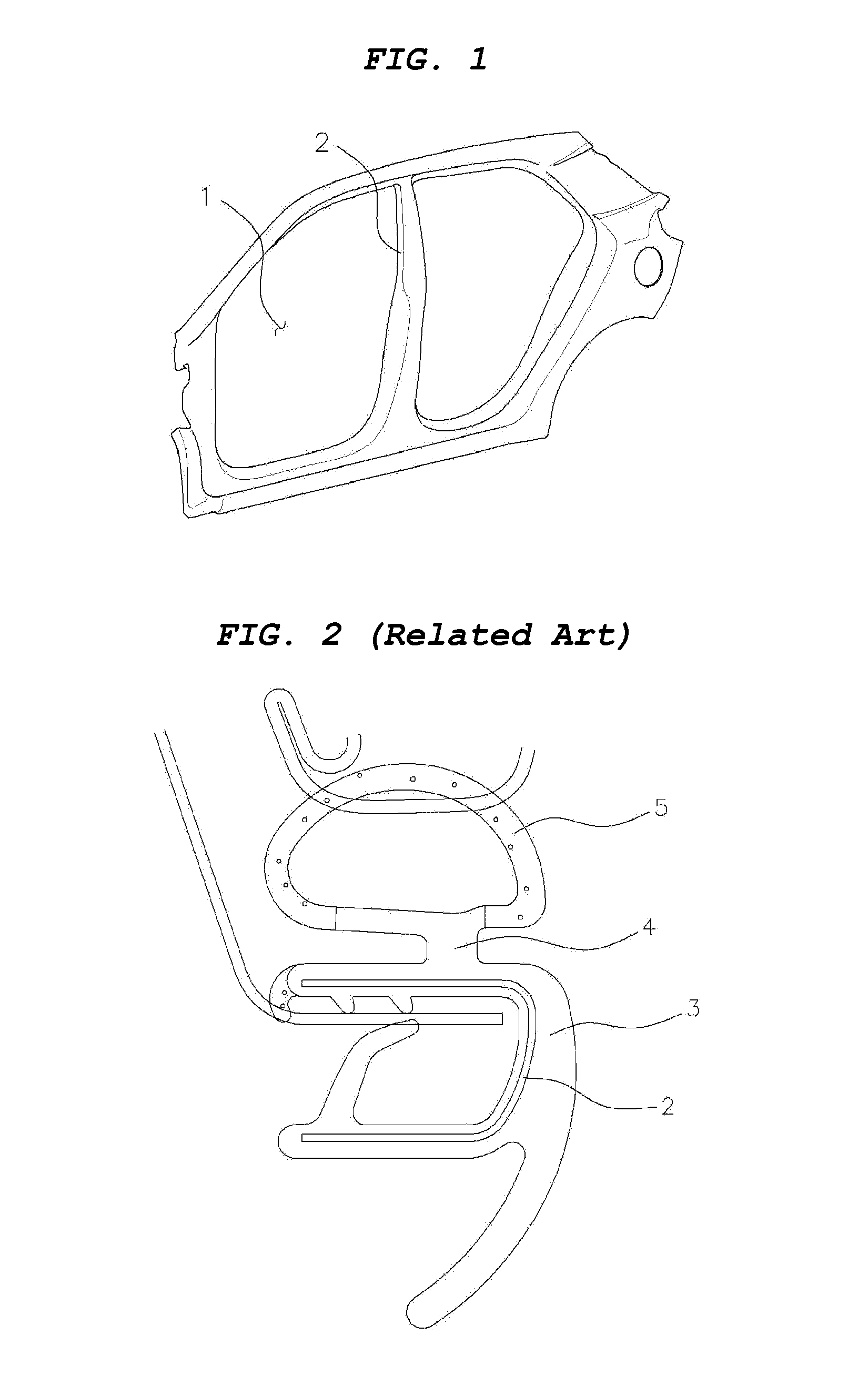
  • Structure of body side weather strip
  • Structure of body side weather strip
  • Structure of body side weather strip

Examples


Embodiment Construction

[0033]Reference will now be made in detail to various embodiments of the present invention(s), examples of which are illustrated in the accompanying drawings and described below. While the invention(s) will be described in conjunction with exemplary embodiments, it will be understood that present description is not intended to limit the invention(s) to those exemplary embodiments. On the contrary, the invention(s) is / are intended to cover not only the exemplary embodiments, but also various alternatives, modifications, equivalents and other embodiments, which may be included within the spirit and scope of the invention as defined by the appended claims.

[0034]A structure of a body side weather strip according to the present invention includes a carrier 20 fixed to a door frame 10 disposed around a door opening of a vehicle body, a first folding portion 30 protruding upward from the top 22 of the carrier and bending horizontally or substantially horizontally, and a cylindrical tube 40...


PUM


Abstract

A structure of a body side weather strip may include a carrier fixed to a door frame disposed around a door opening of a vehicle body, a first folding portion protruding upward from a top of the carrier and bending substantially horizontally, and a cylindrical tube fixed to an end of the first folding portion and the top of the carrier and having a space. When an external force is applied to the tube, the first folding portion may turn about a first rotation shaft such that a bottom of the first folding portion and the top of the carrier may come in surface contact with each other.

Description

CROSS-REFERENCE TO RELATED APPLICATIONS[0001]The present application claims priority of Korean Patent Application Number 10-2013-143439 filed on Nov. 25, 2013, the entire contents of which application is incorporated herein for all purposes by this reference.BACKGROUND OF INVENTION[0002]1. Field of Invention[0003]The present invention relates to a structure of a body side weather strip which is disposed around a door opening of a vehicle body, and more particularly, to a structure of a body side weather strip which has a first folding portion protruding upward from the top of a carrier and bending horizontally or substantially horizontally and a second folding portion formed at one end of a tube and minimizes stress and deformation of the tube shape by folding in two stages when external force is applied.[0004]2. Description of Related Art[0005]A weather strip, which is a part disposed around a fixed glass such as the front rear glasses and the quarter glass of a vehicle or the part...

Claims


Application Information

Patent Timeline
IPC IPC(8): B60J10/00B62D65/08
CPCB60J10/0031B60J10/0088B60J10/0054B60J10/0002B60J10/20B60J10/24B60J10/277B60J10/84
Inventor KIM, JEONG-HYEON
Owner HYUNDAI MOTOR CO LTD
Learn More