
Method of manufacturing optical film for reducing color shift, organic light-emitting display apparatus using optical film for reducing color shift, and method of manufacturing the same

a technology of optical film and color shift reduction, which is applied in the direction of optical elements, instruments, other domestic objects, etc., can solve the problems of reduced service life, low power consumption, and deterioration of materials, and achieve the effect of reducing color shift and color shi

Inactive Publication Date: 2015-05-28
SAMSUNG ELECTRONICS CO LTD
View PDF4 Cites 36 Cited by
  • Summary
  • Abstract
  • Description
  • Claims
  • Application Information

AI Technical Summary

Benefits of technology

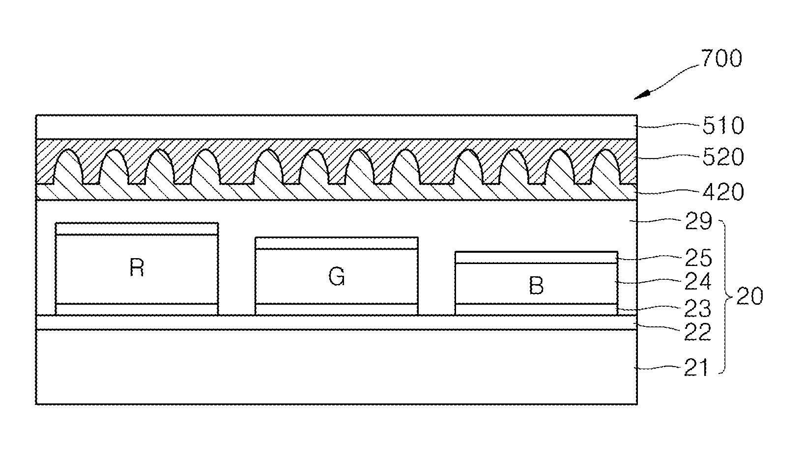
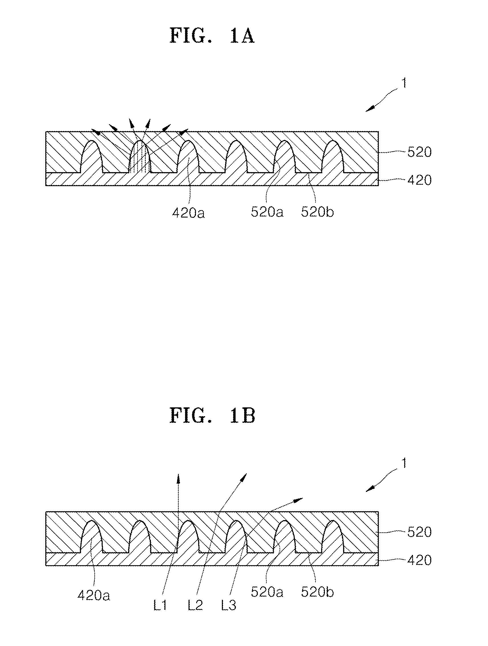
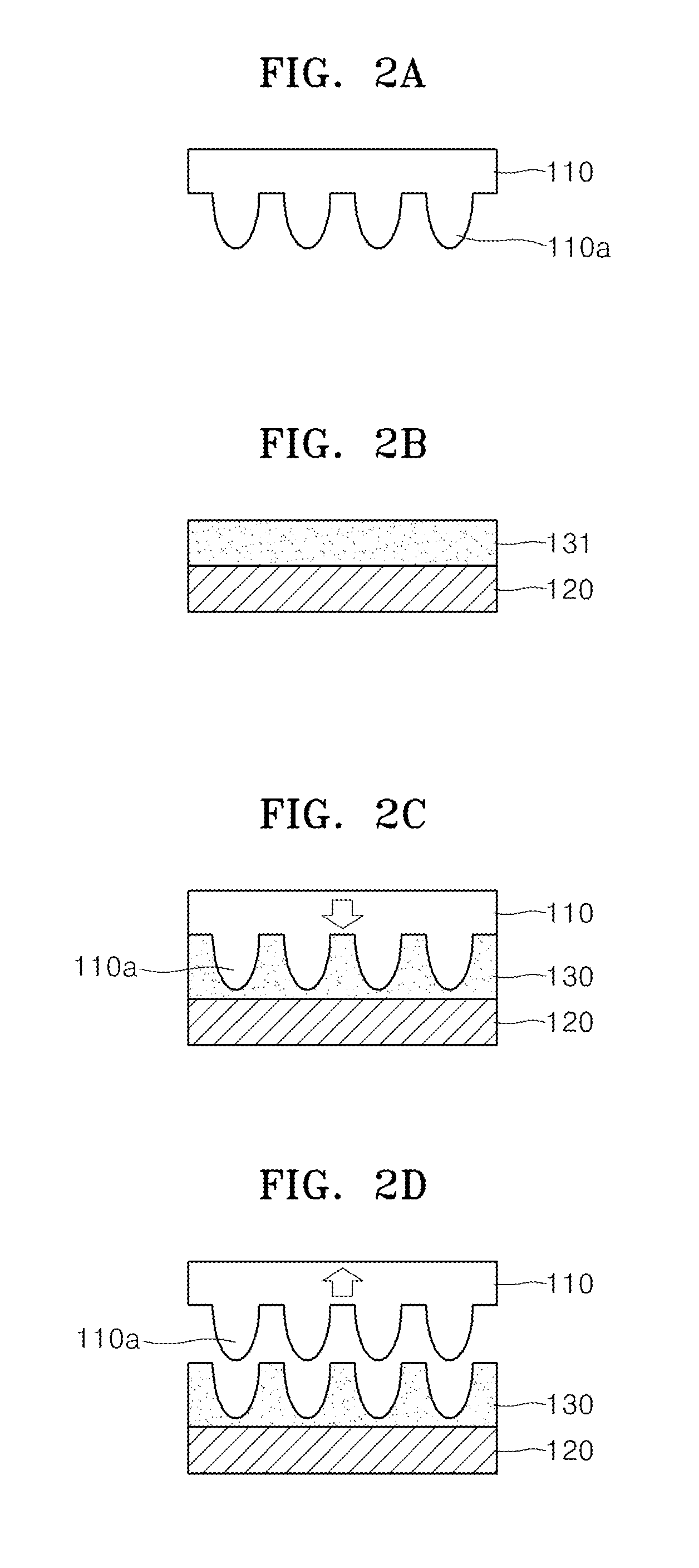
This patent describes methods for manufacturing an optical film and an organic light-emitting display apparatus that can reduce color shifting. The optical film manufacturing method involves forming a master with a shape corresponding to a plurality of micro-lens patterns, using the master to create a low refractive index pattern layer, and then imprinting a high refractive index material layer on top of the low refractive index pattern layer. The high refractive index material layer has a higher refractive index than the low refractive index pattern layer, which helps to separate the two layers without needing a separate release process. The method also includes forming a master using a resin material and a metal mold, and then using the master to create a pattern polymer layer. The optical film can be used in an organic light-emitting display apparatus to reduce color shifting.

Problems solved by technology

In the OLEDs, since a light-emitting material is an organic material, a disadvantage of reduced service life due to deterioration of the material is a fundamental issue in the development of OLED technology, and many technologies are being proposed to address this issue.
Furthermore, the increase in luminance leads to low power consumption, thereby increasing service life.
The optical films for reducing color shift include a micro-lens pattern having a high aspect ratio, and thus, in manufacturing the optical film, defects such as outgassing and void formation occur in a process of filling the micro-lens pattern with a filling material, and hardening and releasing the filling material.

Method used


Image

  • Method of manufacturing optical film for reducing color shift, organic light-emitting display apparatus using optical film for reducing color shift, and method of manufacturing the same
  • Method of manufacturing optical film for reducing color shift, organic light-emitting display apparatus using optical film for reducing color shift, and method of manufacturing the same
  • Method of manufacturing optical film for reducing color shift, organic light-emitting display apparatus using optical film for reducing color shift, and method of manufacturing the same

Examples


Embodiment Construction

[0039]Reference will now be made in detail to example embodiments illustrated in the accompanying drawings, wherein like reference numerals refer to like elements throughout. In this regard, the example embodiments may have different forms and should not be construed as being limited to the descriptions set forth herein. Accordingly, the example embodiments are merely described below, by referring to the figures. Expressions such as “at least one of,” when preceding a list of elements, modify the entire list of elements and do not modify the individual elements of the list.

[0040]Example embodiments may impose various transformations that may have various example embodiments, and specific example embodiments illustrated in the drawings will be described in detail in the detailed description. The effects and features of the example embodiments will become apparent from the following description with reference to the accompanying drawings, which is set forth hereinafter. The example em...


PUM

PropertyMeasurementUnit
refractive indexaaaaaaaaaa

Abstract

An optical film manufacturing method includes forming a master in which a shape corresponding to a plurality of micro-lens patterns is engraved, forming a low refractive index pattern layer in which the plurality of micro-lens patterns are formed, by using the master, forming a high refractive index material layer that has a higher refractive index than a refractive index of the low refractive index pattern layer, and imprinting the low refractive index pattern layer on the high refractive index material layer to form a high refractive index pattern layer, on a first surface of a substrate.

Description

RELATED APPLICATIONS[0001]This application claims priority from Korean Patent Application No. 10-2013-0143152, filed on Nov. 22, 2013, in the Korean Intellectual Property Office, the disclosure of which is incorporated herein in its entirety by reference.BACKGROUND[0002]1. Field[0003]Example embodiments relate to optical films for reducing color shift and / or organic light-emitting display apparatuses using the same.[0004]2. Description of the Related Art[0005]Organic light-emitting diodes (OLEDs) include an anode, an organic emission layer, and a cathode. When a voltage is applied between the anode and the cathode, holes are injected from the anode into the organic emission layer, and electrons are injected from the cathode into the organic emission layer. The holes and electrons injected into the organic emission layer are recombined in the organic emission layer to generate excitons, and the excitons are shifted from an excited state to a ground state to thus emit light.[0006]In t...

Claims


Application Information

Patent Timeline
Patent Type & Authority Applications(United States)
IPC IPC(8): H01L51/56H01L51/52H01L27/32B29D11/00B29C33/38
CPCH01L51/56B29D11/00788B29C33/3885H01L27/3206B29K2907/00H01L51/5265H01L51/5275B29K2029/04B29K2905/00H01L51/5253B29D11/00365H10K59/879G02B5/20G02B5/00H10K50/858
Inventor CHO, EUN-HYOUNGKO, WOONGKIM, JAE-KWANMOON, CHANG-YOULSHIM, HONG-SHIKYOO, IN-KYEONGJEONG, CHUL-HO
Owner SAMSUNG ELECTRONICS CO LTD
Learn More