Combined oil control ring

Inactive Publication Date: 2015-05-28
RIKEN CO LTD
View PDF17 Cites 7 Cited by
  • Summary
  • Abstract
  • Description
  • Claims
  • Application Information

AI Technical Summary

Benefits of technology

The present invention aims to provide a combined oil control ring for automobile engines that can effectively control oil for a long period of operation without getting stuck between the spacer expander and side rails. The invention has a basic structure that allows oil to flow easily from the spacer expander towards both sides, which prevents the accumulation of oil sludge.

Problems solved by technology

The oil sludge attached to and accumulated on engine parts likely wears the parts and clogs lubricating oil paths, causing troubles in the functions of engine parts such as combined oil control rings (called “oil rings” unless otherwise mentioned).
In the oil rings, spacer expanders and side rails are stuck to each other in the worst case, hindering the movement of separate side rails, and thus failing to exhibit a sufficient oil-controlling function.
The accumulation of oil sludge extremely reduces the followability of side rails 120a, 120b to a cylinder wall, resulting in drastically increased oil consumption.
However, the coating methods of JP 2002-310299 A, JP 2003-254155 A, JP 2000-027995 A, JP 2006-258110 A, and WO 2011 / 043364 A1 suffer excess steps leading to cost increase, and the hole-forming method of JUM 59-127856 A need difficult working, making the oil rings expensive.
As a result, sufficient durability is not obtained in such an operation pattern as undergoing repeated stop of engines.

Method used


Image

  • Combined oil control ring
  • Combined oil control ring
  • Combined oil control ring

Examples


example 6

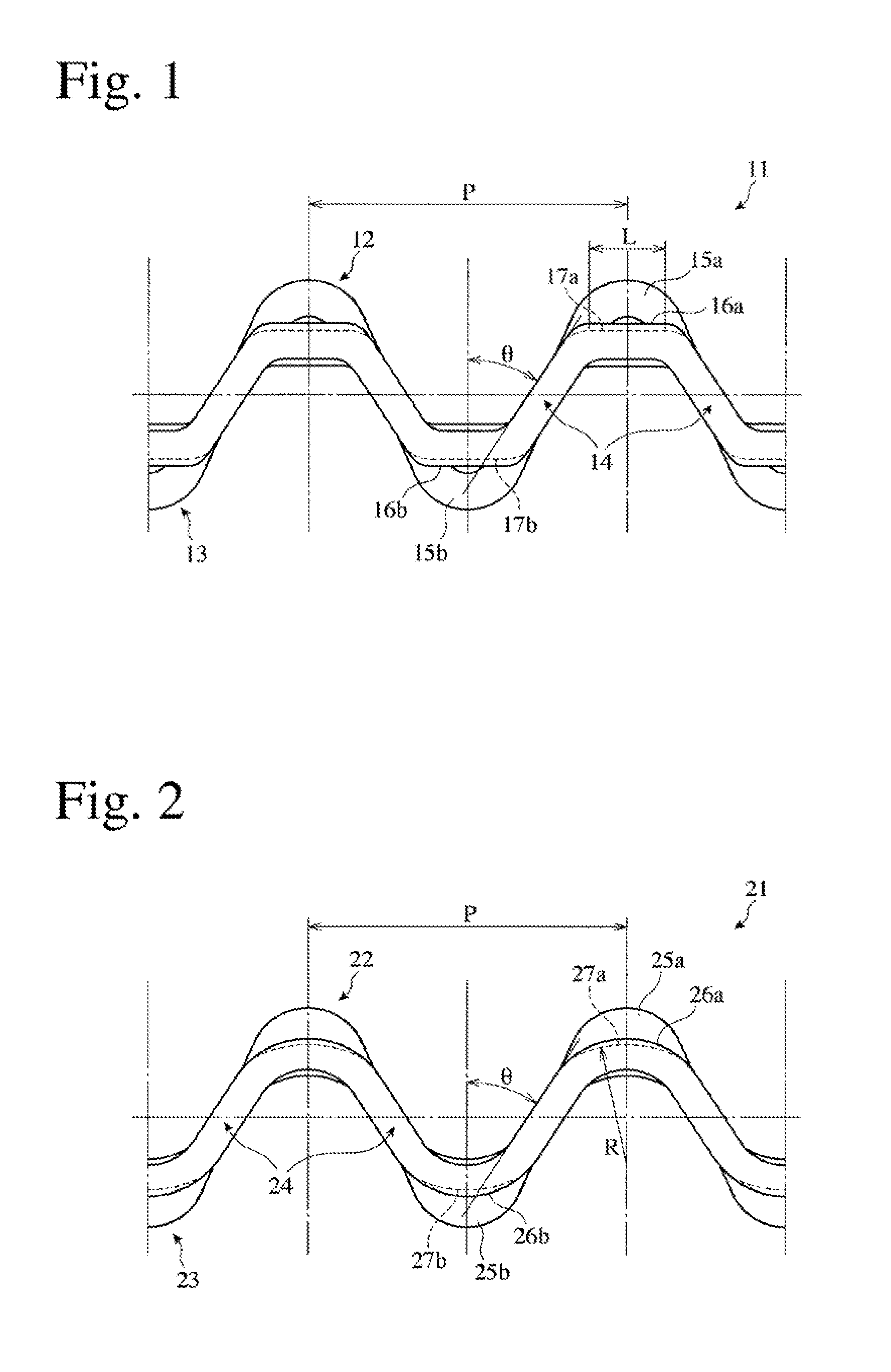
[0045]Combined oil control rings were produced in the same manner as in Example 1, except that intermediate portions of each spacer expander had curved shapes having a radius of curvature of 1 mm and projecting toward opposing side rails in place of the flat pad portions, and mounted to each cylinder of a 3-cylinder engine to carry out the same actual engine test as in Example 1. The measurement results of all cylinders were averaged. As compared with Comparative Example 1, the gap was 1.6 times, and the amount of attached oil sludge was 32%.

example 7

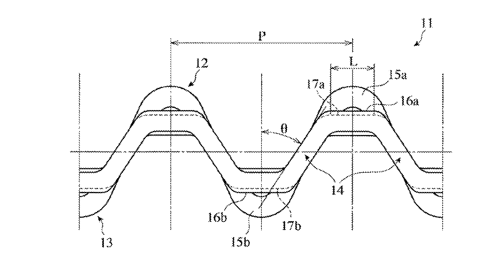
[0046]Combined oil control rings were produced in the same manner as in Example 1, except that each spacer expander was formed to have leg portions with an inclination angle of 18° only in portions near the upper and lower portions and 50° in middle portions between the upper and lower portions, with intermediate flat pad portions having a circumferential length of 0.5 mm, and mounted to each cylinder of a 3-cylinder engine to carry out the same actual engine test as in Example 1. The measurement results of all cylinders were averaged. As compared with Comparative Example 1, the gap was 1.7 times, and the amount of attached oil sludge was 35%.

examples 8-10

[0047]Combined oil control rings were produced in the same manner as in Example 1, except that each spacer expander was formed to have not only leg portions with an inclination angle of 18° only in portions near the upper and lower portions and 50° in middle portions between the upper and lower portions, but also curved shapes having the radius of curvature shown in Table 3 and projecting toward opposing side rails in place of the intermediate flat pad portions, and mounted to each cylinder of a 3-cylinder engine to carry out the same actual engine test as in Example 1. The measurement results of the actual engine test conducted 3 times were averaged, and are shown in Table 3.

TABLE 3Radius ofCurvature R ofAmount ofInclinationIntermediateAttached OilNo.Angle θ* (°)Portions (mm)S2 / S1SludgeExample 8500.516536Example 9501.516834Example 10502.015541Note:*Inclination angle of the leg portions in middle portions between the upper and lower portions.

[0048]Examples 8-10 were excellent in bot...


PUM


Abstract

A combined oil control ring for automobile engines capable of keeping an excellent oil-controlling function without suffering sticking between a spacer expander and side rails for a long period of operation comprises upper and lower two side rails, and an axially corrugated spacer expander having upper and lower portions; a leg portion connecting each upper portion and each lower portion of the spacer expander having a portion having an inclination angle θ of 15° or more from the axial direction.

Description

FIELD OF THE INVENTION[0001]The present invention relates to a combined oil control ring mounted to a piston for an internal combustion engine, particularly to a combined oil control ring comprising two upper and lower side rails, and an axially corrugated spacer expander having upper and lower portions.BACKGROUND OF THE INVENTION[0002]In automobile engines, a lubricating oil is heated and exposed to a blowby gas during a long period of operation, so that the lubricating oil is contaminated with unburned hydrocarbons and degenerated oil additives (called “oil sludge” as a whole). The oil sludge includes oil sludge precursors having relatively high viscosity. The oil sludge attached to and accumulated on engine parts likely wears the parts and clogs lubricating oil paths, causing troubles in the functions of engine parts such as combined oil control rings (called “oil rings” unless otherwise mentioned). In the oil rings, spacer expanders and side rails are stuck to each other in the ...

Claims


Application Information

Patent Timeline
IPC IPC(8): F16J9/06
CPCF16J9/068F16J9/06F16J9/064F16J9/066F16J9/12F16J9/203
Inventor OOYA, YOSHIHITO
Owner RIKEN CO LTD
Why Eureka
Try Eureka