

Display apparatus
- Summary
- Abstract
- Description
- Claims
- Application Information
AI Technical Summary
Benefits of technology
Problems solved by technology
Method used
Image

Examples
first embodiment
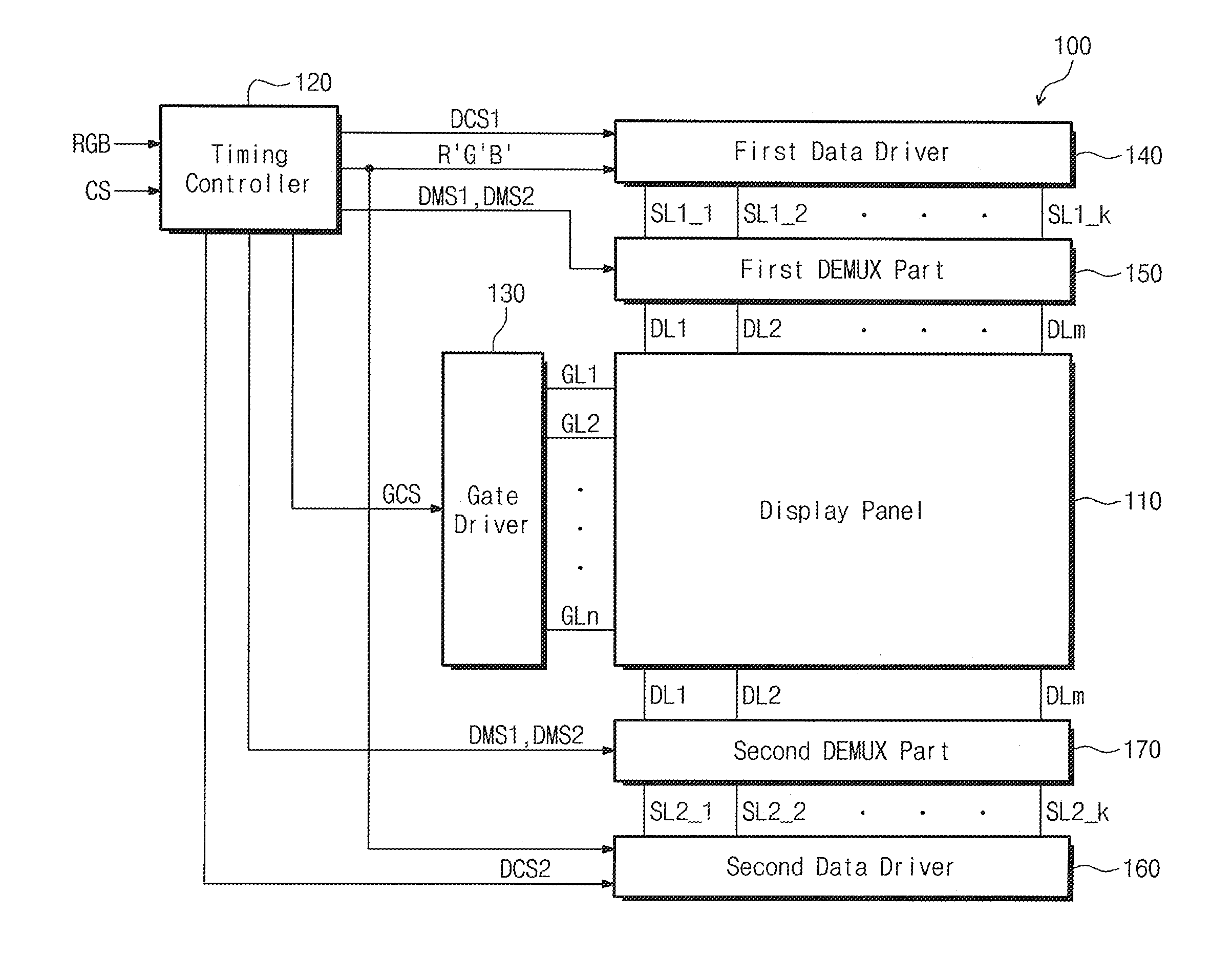
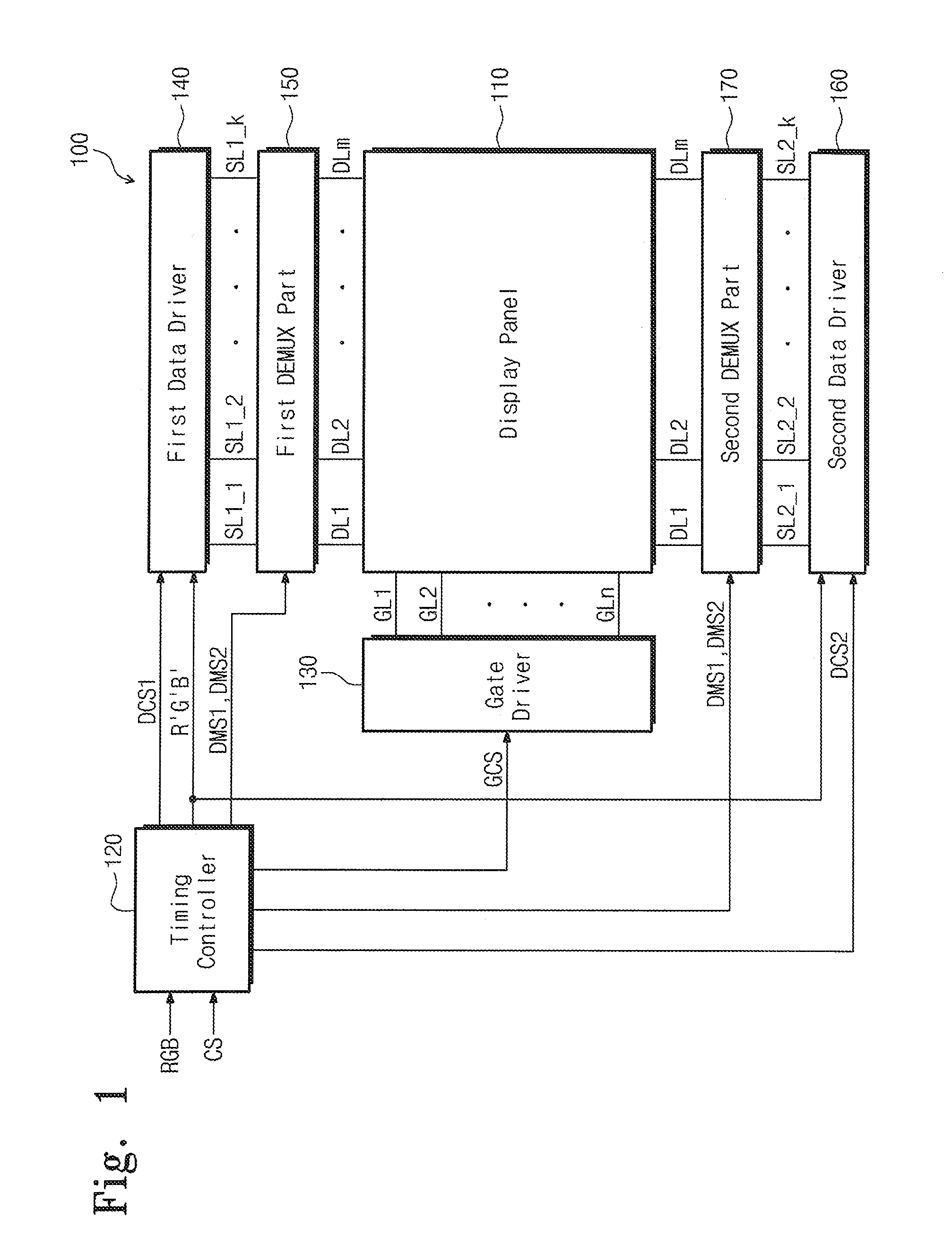
[0074]FIG. 1 is a block diagram showing a display apparatus according to the present disclosure.
[0075]Referring to FIG. 1, a display apparatus 100 includes a display panel 110, a timing controller 120, a gate driver 130, a first data driver 140, a first DEMUX part 150, a second data driver 160, a second DEMUX part 170, a plurality of gate lines GL1 to GLn, a plurality of data lines DL1 to DLm, a plurality of first signal lines SL1_1 to SL1—k, and a plurality of second signals lines SL2_1 to SL2—k.
[0076]The display panel 110 includes a plurality of pixels arranged in a matrix form. The gate lines GL1 to GLn may extend in a row direction, and are coupled to (e.g., connected to) the gate driver 130 and the display panel 110. Here, “n” is an integer number greater than zero (0).
[0077]The data lines DL1 to DLm may extend in a column direction, and are coupled to the first DEMUX part 150, which may be positioned (e.g., disposed) adjacent to an upper portion of the display panel 110 and t...
second embodiment
[0161]FIG. 6 is a circuit diagram showing a display apparatus 200 according to the present disclosure. The display apparatus 200 has a substantially similar configuration and function as those of the display apparatus 100 shown in FIGS. 1 and 2, except for the first and second DEMUX parts. Therefore, the description of the substantially similar portions thereof have been omitted.
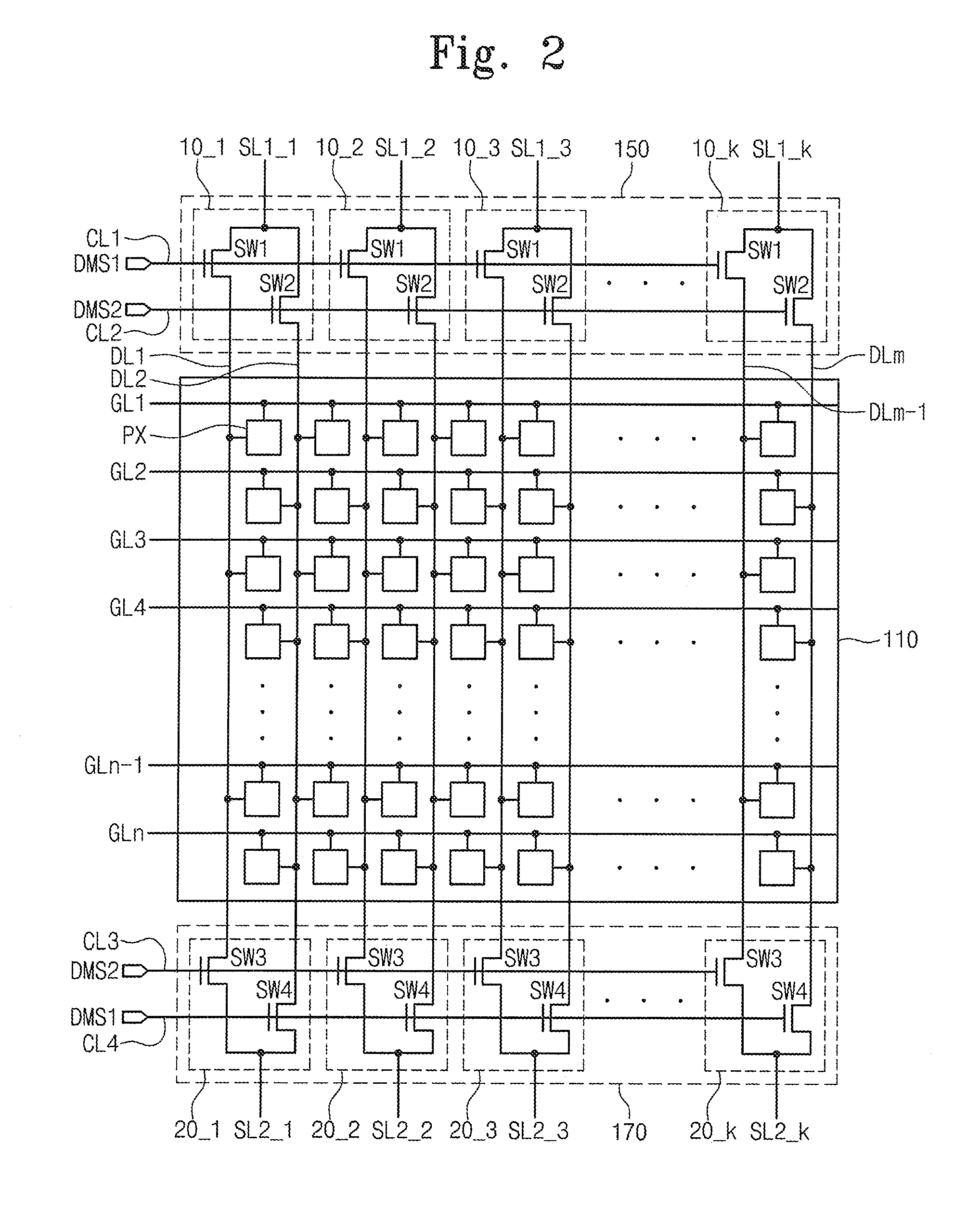
[0162]Referring to FIG. 6, each of the first DEMUX units 10_1 to 10—k includes a first switching device SW1 coupled to (e.g., connected to) a first control line CL1, and a second switching device SW2 coupled to a second control line CL2. Each of second DEMUX units 20_1 to 20—k includes a third switching device SW3 coupled to a third control line CL3 and a fourth switching device SW4 coupled to a fourth control line CL4.
[0163]The first and fourth switching devices SW1 and SW4 are switched in response to the first DEMUX signal DMS1 provided through the first and fourth control lines CL1 and CL4. The second and...
third embodiment
[0237]FIG. 15 is a circuit diagram showing a display apparatus according to the present disclosure.
[0238]Referring to FIG. 15, each of first DEMUX units 10_1 to 10—k includes a first switching device SW1 coupled to a first control line CL1, and a second switching device SW2 coupled to a second control line CL2. Each of second DEMUX units 20_1 to 20—k includes a third switching device SW3 coupled to a third control line CL3, and a fourth switching device SW4 coupled to a fourth control line CL4.
[0239]The first and fourth switching devices SW1 and SW4 are switched in response to the first DEMUX signal DMS1 provided through the first and fourth control lines CL1 and CL4. The second and third switching devices SW2 and SW3 are switched in response to the second DEMUX signal DMS2 provided through the second and third control lines CL2 and CL3.
[0240]The first and second switching devices SW1 and SW2 couple first signal lines SL1_1 to SL1—k to corresponding first and second data lines DL1 t...
PUM
 Abstract
Description
Claims
Application Information